
Images by Jody Culkin & Eric Hagan. Used with permission from Arduino to Go
Introduction
If you’re looking for project ideas, please check our Workshops!
What is physical computing?
Physical computing refers to the process of building physical interfaces that respond to the analog world. This is done by building circuits with microcontrollers, wires, sensors, LEDs, motors etc. and controlling them with a piece of custom-made software (i.e: “Turn the LED on when the number sent by the photocell sensor is less than 100”). Physical computing is a great way of introducing or reinforcing programming concepts, and exploring how they can be applied to non-screenbased applications. But it has also been used beyond the educational realm – by artists, to support ALS patients, for immersive installations, experimental music, fashion, and to test water quality.
While there are a lot of similarities between robotics and physical computing, the latter is focused on creating interfaces that explore the human body’s relationship to the digital world (rather than building robots that can function without human or environmental input).
Using A Microcontroller
What’s a Microcontroller?
A microcontroller is a small computer that can take in information from inputs such as sensors and switches and control outputs such as lights, motors and other computers. Microcontrollers are widely used in many different ways; DIY and robotics, art installations, industrial applications, and the internet of things.
When you are using a microcontroller, or in our case a microcontroller platform, there are two components: hardware and software. The hardware includes the microcontoller and its input and output pins, and any input or output devices you want to attach to it. The software is programs you write that control the microcontroller and the devices you have attached to it.
In the Makerspace, we will be mainly using the Arduino microcontroller platform. It was developed by a team of teachers to help their design students who were not engineers create physical interfaces.

To learn more about the parts of a microcontroller, specifically the Arduino Uno, check out Arduino To Go!
What’s an IDE?
An IDE, or integrated development environment, is a software application that allows you to write code and test that code out in the programming language the IDE supports.

The Arduino has an IDE, (integrated development environment), that is free and downloadable from the Arduino site (download it here). This is a set of software that allows you to write code, then upload it directly to the Arduino. The computers in the Makerspace have it already installed. (If not, tell the Lab Manager!)

If you have experience programming, you may have used another IDE to write, test, debug, and turn your code into something the computer understands. If you haven’t, the Arduino IDE is a good place to start, as it is relatively simple and easy to understand.
Settings in the software:
We have seen a bit about the parts of the Arduino and we have seen that we program it through the Arduino software. Before we start programming the Arduino, we have to set a couple of settings in the software to ensure that the Arduino can communicate with your computer.
Load the Arduino software. Once it is loaded, go to the To do this, go to the Tools menu, select Board. From the fly out menu, select Arduino Uno/Genuino.
It is also necessary to specify a Serial Port for your Arduino to communicate with the computer. A Port is a channel of communication which connects your Arduino and the computer. On a Windows machine, go to the Tools Menu, select Port then select the COM port that is specified. It should look something like the screenshot below.
Once you have connected the Arduino to the computer and set the version and the port, you are ready to start programming the Arduino.
Coding With The IDE
The IDE also comes with several pre-made codes for electronics projects to get you started! Here in the makerspace, our go-tos for beginners are the Blink and Button sketches! A Sketch is what we call the fully coded program that is uploaded into the Arduino via the IDE.

Coding can be difficult to understand at first, but never fear! Arduino To Go has a helpful walk through, and the Arduino site proper has Tutorials and a Reference page for particular bits of code. The Forum is also a great resource to help you troubleshoot any issues you might have!
Always, always make sure to Verify your code in the IDE before uploading!

Make a Circuit (With Me)
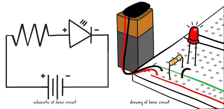
The circuit is the basic building block for any electronics project. A circuit includes all of the electronic components required for a task as well as wires or another material which will let the electricity flow between the connected components. Electronic circuits describe a complete and closed loop.

There are two main parts that make up a circuit: conductive lines and components. What are components? LEDs, transistors, resistors, diodes, and all of the parts that control the flow of electricity or have another function in our circuit. Conductive lines are often metal threads or wires we call jumpers, as metal is a good conductor of electricity. Conductivity is the state by which something can carry an electric charge. Metals like copper, aluminum, and tin are conductive, which many electronic components are made out of.
Not all circuits have to be wires! What we call soft circuitry, is using “soft” materials to make a circuit. Thus could be conductive threads, fabrics, inks (made of carbon and silver), and even play dough (the salts in the dough make it conductive)!
The Breadboard
Components are often attached to each other on a solderless breadboard. What’s that? A solderless breadboard has rows and columns of metal strips encased in plastic with a grid of holes called tie-points on the top. It allows us to quickly build circuits without having to permanently connect the components (by soldering, for example).
There is a pattern to how the metal strips are arranged on a breadboard. There are long strips along the left and right of many breadboards that are used to attach power and ground in a circuit. These long columns are called buses. The power bus is marked with a red plus sign, the ground bus with a green, blue or black minus sign.


Breadboards come in many sizes, from tiny to massive! The most commonly used ones are referred to as Half-Size (with 30 rows), and Full-Size (with 60 rows). For many of our projects in the makerspace, we only need a half size board. And you’ll with many of our examples use one too.
How do you connect a breadboard to an Arduino to build a circuit? Depending on the circuit, you’ll use different components, sensors and kind of a wire we call jumpers and connect them to certain ports on the Arduino. Read on to learn about some of the components used commonly in the makerspace. This is not the definitive list, as there are plenty of other kinds out there, so don’t be afraid to research and try something new!
Power & Ground
As stated before, a circuit is essentially a closed loop of electrical flow. A power supply provides power (+), and goes to a ground (-) in a closed loop. The components set up in the breadboard go along this loop.

A visual representation of that is called a schematic. Schematics can be daunting to read at first, and in the makerspace we tend to use guides that are schematic-free, but they are important part in going further in your physical computing journey.
Inputs & Outputs
Inputs are usually sensors, buttons, switches– anything that puts in data to be read by the microcontroller. Outputs are things like LEDs, screens, speakers, anything that puts out the data read by the microcontroller.
Think of your tongue as a sensor, your brain as the microcontroller. You eat a ghost pepper and it’s very spicy! Your tongue feeds data to your brain, your brain processes the data and determines it’s spicy– because it is coded to react to different kind of flavors, and how your brain tells you to react to the spice is the output. You might grimace, or tear up, or go dashing for something to cool it off!
There are two kinds of inputs/outputs, and that is Digital and Analog.
Digital inputs/outputs are binary, meaning they only have two options, or states. On (1) or Off (0). A good example of a digital input is a pushbutton. The digital output would the light turning on or off.
Analog inputs/outputs can hold a range of values that is nonbinary. In the Arduino code, this range is usually mapped to fit a range between 0 and 1024. A good example of an analog input would be a potentiometer (a sort of dial– more on that later). The analog output is the brightness of the light grows or dims.
LEDs, Resistors, and Sensors, Oh My!

There are many kinds of components, made by many different manufacturers. It is very good practice to know the item’s part name code and have the data sheet for it or reference!
An LED (light emitting diode) has an orientation, or a positive and negative lead. An LED must be placed into a circuit properly, with the positive and negative lead oriented properly. How do you know what is the positive and negative side? The positive side has a longer lead. It is called the anode. The negative lead is shorter and called the cathode. Also, the negative side of an LED often has a flatter side at the bulb.

A resistor is a component made from carbon film (in some cases ceramic), that is used to create resistance in the flow of electricity in the circuit, and it often used in tandem with other components. Resistors come in a variety of resistance, measured in a measurement called ohms. On carbon film resistors (the ones we use in the makerspace) have a system of bands to determine the kind of resistor it is. Thankfully in this day and age, there’s plenty of charts and guides out there to help you determine what is, even apps for your phone! But another way is the old fashion test-with-a-multimeter method. (More on that further down).

Buttons are somewhat self explanatory; you push them and they do things. There are two types of buttons momentary buttons that only react when pushed (say like your keyboard buttons), and maintained, where one need to press it to turn on and the once again to turn it off.
Switches are like maintained buttons, only has two states, determined which direction the switch is facing. A light switch is the most obvious example.
Potentiometers are a variable resistor. As explained before they can displace a range of states. This is done by changing the resistance in the circuit. Volume dials are potentiometers.
Sensors are any device that is uses to measure any kind of input. There are a lot of sensors. A lot. In the makerspace we have force sensing resistors (sensing pressure), photosensors (sense light or lack thereof), accelerometers and tilt sensors (direction), and infrared sensors (sense waves of infrared).
Speakers output sound. On top of the speakers you may know that create all various kinds of sounds, in the makerspace we use piezoelectric speakers, which emit a buzzing tone that can be altered. You might have experienced a piezo speaker in one of those music-playing cards.
Motors output motion. Some of the kinds of motors are DC (direct current) motors, stepper motors, and servo motors. DC motors provide a continuous spin (used in RC Cars), servo motors can be programmed to move at increments (used in robotics). Stepper motors similar to DC motors but are slower more precise (used in 3d printers).
Some other components you’ll come across as you explore further into physical computing are Capacitors, Transistors, Diodes, and more! These are used in a more advanced things than we do in the makerspace, but it’s nice to be aware of them.

The Shocking Truth: All About Electricity
Power supplies are key to a circuit. Batteries are usually the go-to for smaller electronics, power supply machines exist that allow you to control the voltage and amperes (more on that below!), for some projects, you may need to plug it in. You’ve not need to worry too much since your power for your circuits so far was coming from your computer via the USB to your Arduino. But as you explore further and create different projects that you want to stand alone, you are going to have learn about power!
The Current Event

Current is is how fast the flow of electrons (particles that carry a charge and generate the electricity we use– and the very same particles that create the outer shell of atoms!) going to ground in the circuit. Some people equate current to water in a hose and some people use a roller derby to explain. Current is measured in amperes, or more commonly known as amps.
There are two kinds of currents. Alternating Current (AC) can change direction, and is the kind of electricity used to power houses. It is the kind of power you get from your wall socket. Direct Current (DC) cannot and flows only in one direction. Batteries are the sort of power that carries direct current.
Resistance is when the flow of the current is slowed down and resisted. Going with the hose example, resistance would be akin to you putting your foot on the hose. It doesn’t stop the flow, but less water comes out. This is measured in ohms. (A thing to note– electricity, like us, is kind of lazy. It will always want to flow to the place of least resistance in the circuit.)
Voltage is the amount of energy between two points of the circuit. Normally one point has a higher voltage than the other. It does sound similar to current, but following the water analogy, current it flow of the water, voltage is the water pressure.
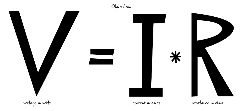
The three measurements are intimately linked with one another, and measured in a sort of equation called Ohm’s Law. This explains that the current of the circuit will always be related to resistance and voltage inside it as well. It’s easier to understand seeing the equations.

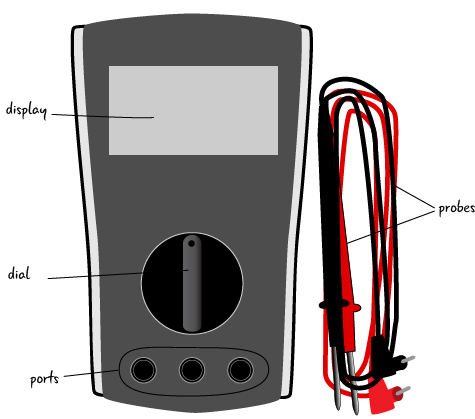
To measure any of these three elements, you will need a tool called a multimeter.
This device is diagnostic tool, and key to have when working with electronics. It consists of a screen, two probes, ports to place those probes, and a dial that changes to measure what you’re looking for (volts, ohms, DC and AC amps).
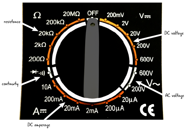
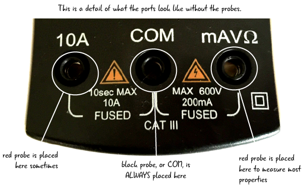
Here is more in depth instructions for using the multimeter to troubleshoot your circuits.
Going to Ground: Conclusion
If you haven’t realized by reaching this point, physical computing can be a lot to take up at the start. It can come off as frustrating and intimidating, but know that there are plenty of resources (like this site!) out there to help you on your journey. And in the words of Ms. Frizzle: “Take chances, make mistakes, and get messy!”
Tutorials
- Introduction to Physical Computing
- Introduction to Physical Computing (Virtual)
- Squishy Circuits Workshop
- DIY conductive Ink
- Soft Circuits by Sparkfun
- DIY Light-Up Card from Instructables
Other Resources
Check our Resources page on where to purchase materials.
- Getting Started with Arduino
- Introduction to Arduino on Arduino to go
- Physical Computing page at ITP NYU
- “Massimo Banzi: How Arduino is open-Sourcing imagination”
- Physical Computing Projects on Adafruit
- Sparkfun’s Adventures in Science YouTube Playlist
- Jeff Feddersen’s Videos on Physical Computing & Electricity
- All About Circuits
- Resistor Code Calculator
- Ohm’s Law Calculator
- Electrical Symbols Guide (For Datasheets and Schematics)
- Reading a Schematic