If you have been to or have read our Physical Computing Workshop and all of this looks familiar– it is! The difference between that workshop and this one is that this is designed to be done entirely virtually through Tinkercad’s Circuit Simulator. This is great if you cannot obtain an Arduino kit for any reason, but still would like to learn and experiment with it.
Before starting, you can make a Tinkercad account if you haven’t already, as well as installing the Arduino IDE. You can also just make an account with Arduino and use their browser based version of the editor. If you are using one of the machines from the Makerspace, it should be already installed on it.
The procedure for downloading and installing the software is slightly different for Macs and Windows. Detailed instructions for both platforms are here.
What is Physical Computing?
Physical computing refers to the process of building physical interfaces that respond to the analog world. This is done by building circuits with microcontrollers and components designed to to do a certain purpose. LEDs light up, potentiomenters change resistance, motors turn, et cetera. This is all done through the electricity going through the circuit.
However, we won’t go too in depth with this, if you’d like to learn more and explore this further, you can read up about it in detail in our Physical Computing Overview.
A Look at the Arduino Uno:
A microcontroller is a small computer that can take in information from inputs such as sensors and switches and control outputs such as lights, motors and other computers. Microcontrollers are widely used in many different ways; DIY and robotics, art installations, industrial applications, and the internet of things.
When you are using a microcontroller, or in our case a microcontroller platform, there are two components: hardware and software. The hardware includes the microcontroller and its input and output pins, and any input or output devices you want to attach to it. The software is programs you write that control the microcontroller and the devices you have attached to it.
We will be using the Arduino microcontroller platform. It was developed by a team of teachers to help their design students who were not engineers create physical interfaces. There are many different Arduinos, and clones as well. We will be using the Uno.
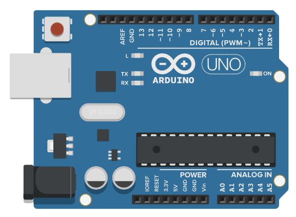
To learn more about the parts of a microcontroller, specifically the Arduino Uno, check out Arduino To Go!
This is where we’re veering off a bit from the other workshop, as everything is virtual, we do not need to plug in the Arduino. But we are going to look at the native Arduino IDE and code from there. The circuit simulator does have a built in IDE as well, but it’s a nice to also be familiar with the Arduino IDE as well.
A Look at the Breadboard:
A breadboard is a part that allows you to prototype and troubleshoot circuits quickly without needing to commit to them. The board we will be using is called a half sized breadboard.
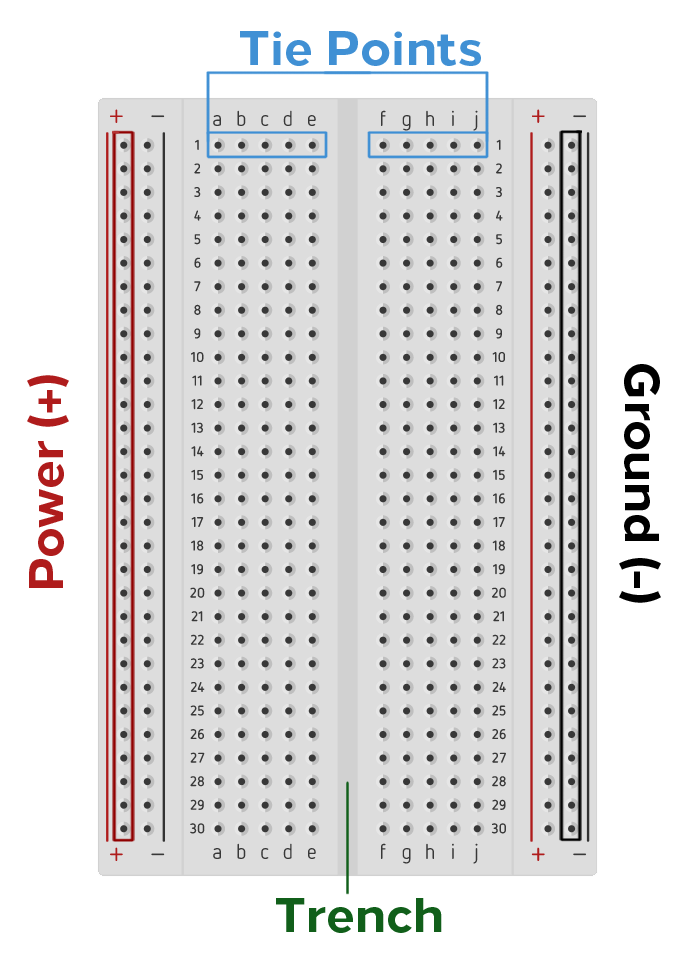
As you can see there’s all these little holes, and it can get confusing to look at for the first time. The two rows on each end of the board marked with a plus (+) or minus (-) sign is the power and ground rows. Power is plus (+), and ground is (-). This is where you connect your power source and ground from the Arduino. these are marked with 3.3V, 5V (the amount of power we’re sending to the board in volts) and GND (which there are two pins as well.) It’s important to know, as getting these mixed up could cause a short and circuit and will not work.
The rows labeled with numbers and letters are tie points, these are where your components and wires go into. You have two sets of tie points, separated by a trench. This gap allows you to use larger sized components (you will see later with the pushbutton). The numbers (1-30) indicates rows and the letters (a-j) indicate columns.
Inside, they have copper strips inside them to make them conductive, which is how these rows work. Here’s what it looks like:
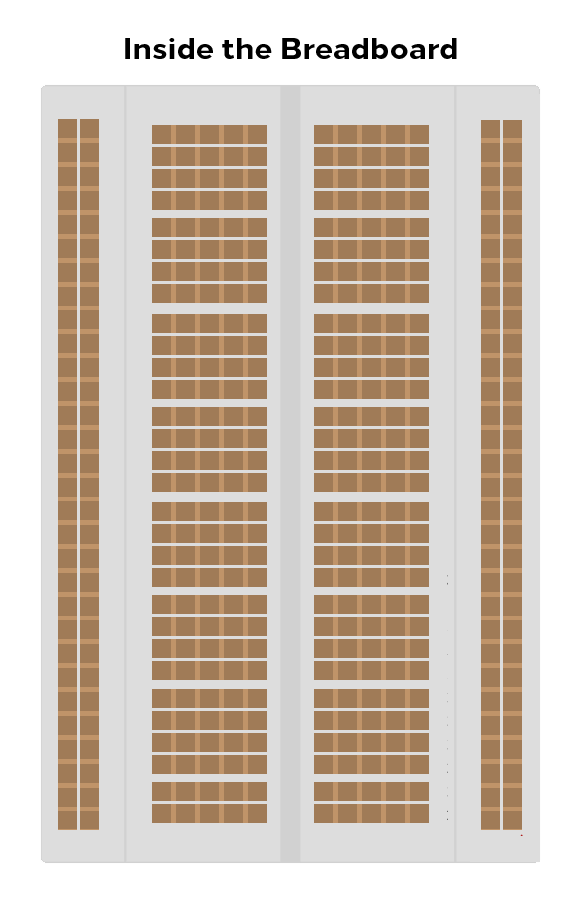
The power and ground rows on the breadboard run vertically (up and down) from the board, while the tie points run horizontally (left to right) on the board. You can’t put all the pins of a component on the same row of tie points, or it won’t work, but they can run the same column. So one leg or pin can go into 5c (row 5, column c), and the other can go anywhere else on the c column to work.
(It should be noted this paragraph is using the upright board as a reference. It’s more likely that your board will be on it’s side in the simulator, so your tie points will be vertical and your power and ground horizontal in that case.)
What’s an IDE?
An IDE, or integrated development environment, is a software application that allows you to write code and test that code out in the programming language the IDE supports. The Arduino has an IDE, (integrated development environment), that is free and downloadable from the Arduino site (linked above). This is a set of software that allows you to write code, then upload it directly to the Arduino.
Setting Up the IDE:
If you have not installed it before starting this workshop, please do so now. The links are provided above in the beginning, or download HERE. Or open up the browser editor after making an account.
Once you have finished installing your IDE, start it up. We will still need to set it up as if we were going to use an actual Arduino for this project.
The icon should look like this (or something similar):

Once it starts, you should see a window, like so:
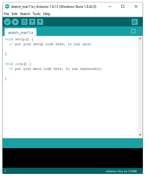
This is called our Sketch. It is the code we will use to make our Arduino do things. Think of the code as thoughts, the Arduino as a brain and our components as our body parts. It tells the brain what to do and with what body part.
If you have problems reading the sketch, you can adjust it for your comfort. You can expand it to be the full window. And if you go to File > Preferences to adjust certain settings, like text size and other features.
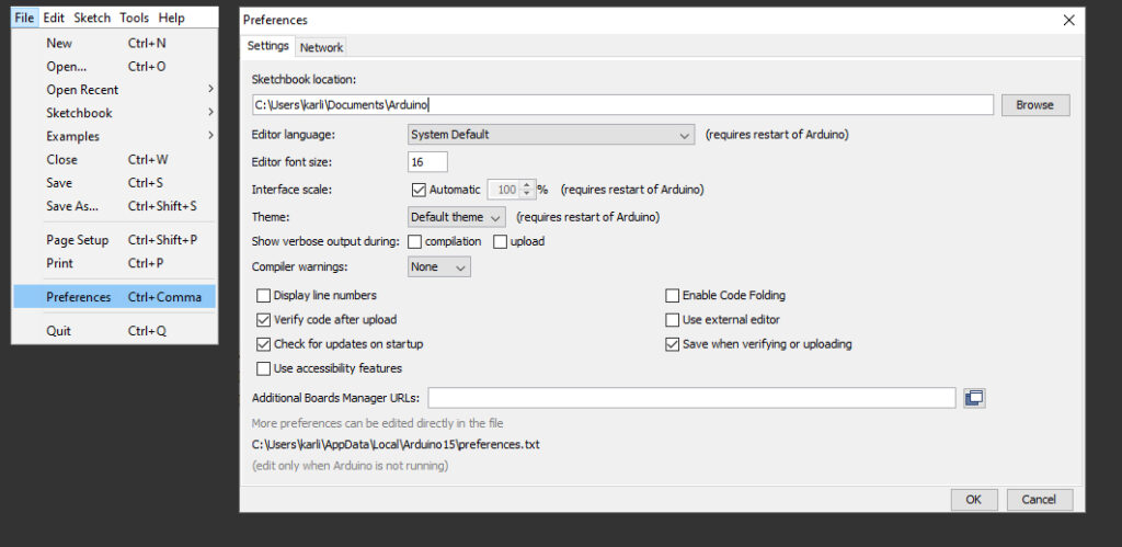
Unfortunately, Adruino does not have a default dark mode, but I can recommend konradhtc’s One Dark Arduino theme. Following the link will show you how to download and install it.
(For the sake of brevity I will be continuing to use the light theme, but I set my text at 16 points for me to read better.)
When you have finished setting up your IDE settings, we must make sure it’s set to the right Arduino that we are using, as there are many different models. Go to Tools > Board > Arduino Uno.
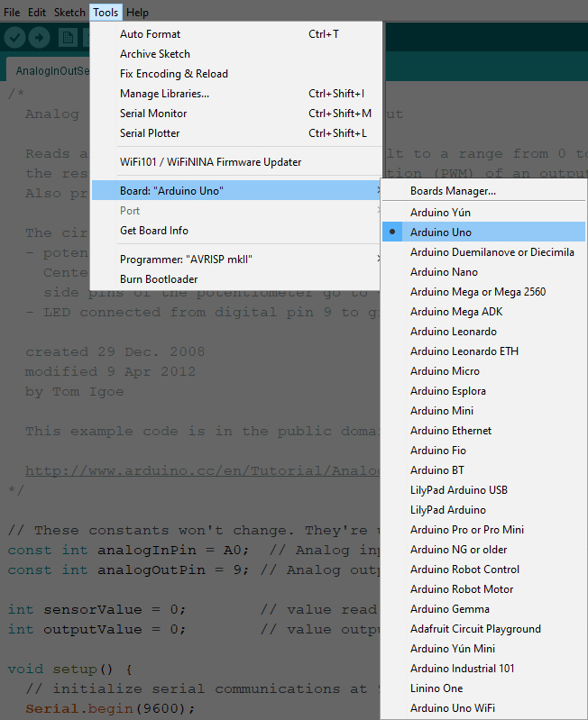
It should be the default, but it doesn’t hurt to check. Since this is virtual, we do not need to check the Ports like we would the physical setup. We are now ready to code!
But before we code, we need to set up the circuit.
Creating a Tinkercad Account:
If you already have a Tinkercad account, please login and scroll down to Tinkercad Circuit Simulator. Otherwise, follow along at this point.
Isn’t Tinkercad that 3D modeling site? Well, yes it is. But it provides not just 3D! This is fairly recent development added on to the site, which is a really good way to learn electronics in a pinch.
On the upper right corner of the main site, click JOIN NOW.

Next, select Create a Personal Account

Select Sign Up with Email

Select your country, and your birthdate, then hit NEXT.

Put in the email you wish to use and a password. It needs to be a minimum of 8 characters, at least 1 letter and 1 number, and at least 3 unique characters

Click the box to agree to Autodesk’s Terms of Service, then select CREATE ACCOUNT

They will take you through a 3D tutorial, but skip it for now. You can revisit it later at any time.
Tinkercad Circuit Simulator:
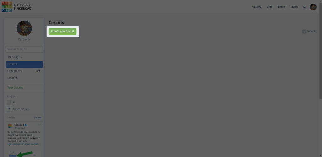
Your Dashboard will default to your 3D designs. On the left side of your dashboard, underneath 3D Designs, you’ll see an entry called Circuits.
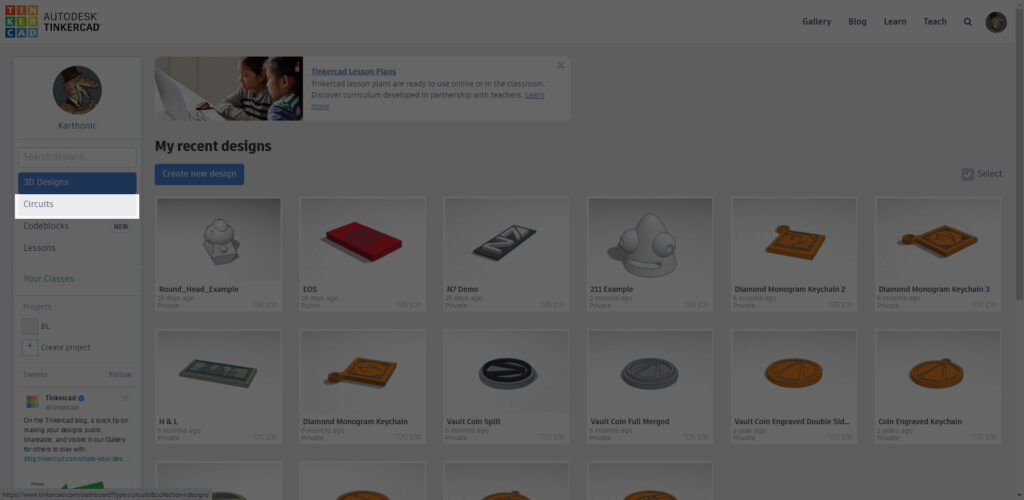
Select that, that will take you to your Circuits dashboard.
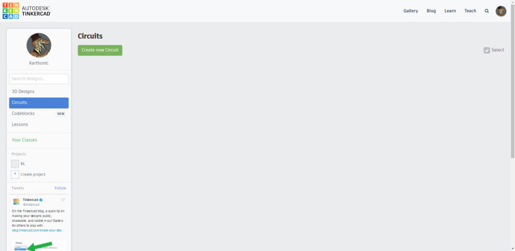
Click Create New Design, the big green button.
This is our workspace, the actual user interface is even more pared down compared to the 3D modeling one.
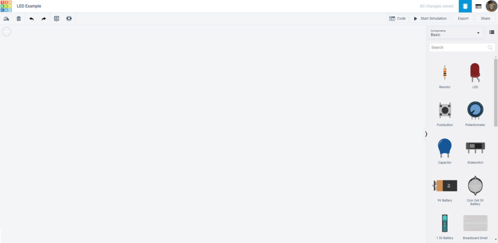
At the top, you will see a randomly generated name. You can rename your project by clicking on it and changing the name.

On the left side you have your Rotate tool (Shift + R), your Delete button (Delete), your Undo (Ctrl/Cmd + Z ) and Redo (Ctrl/Cmd + Y), Annotations (for making notes), and View/Hide to view or hide your notes. Just below that is a Zoom to Fit (Z) button, but you can use the Ctrl/Cmd and + or – keys to zoom in or out.
Don’t worry about remembering shortcuts, they will be listed at the bottom of this page!
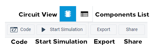
On the top right we have our Circuit View button (it looks like a little bug– but in reality it’s a microchip), next to that is the Components List. When you add components it will make a neat list of what you have.
Below it is the Code button, where we will put the code from the IDE on later, the Start Simulation button, which will allow us to simulate everything once we have everything together. Export will export your board for Eagle, which is software used to make circuit boards. Share allows you to download a snapshot of the circuit or invite other users to collaborate on it.
Below that are your components. These are what makes your circuit.

You can search for a particular part in the Search Bar, or in the dropdown, there are more options, including pre-made Arduino circuits. Great to explore later once you’ve built your own.

Selecting the but to the right of the dropbox gives you a simple definition of the components.

Now it is time to build your first circuit!
Building Your Circuit:
First, we want the Small Breadboard. Find and drag it onto your workspace.
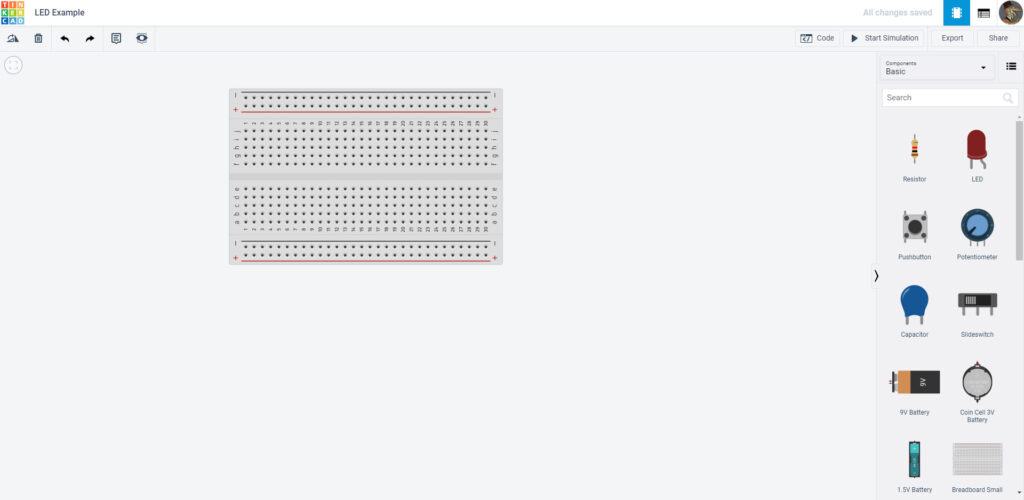
Next find the Arduino Uno R3.It should be under the breadboard if you scroll down.
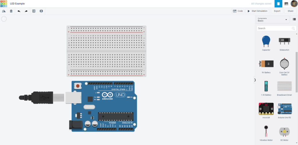
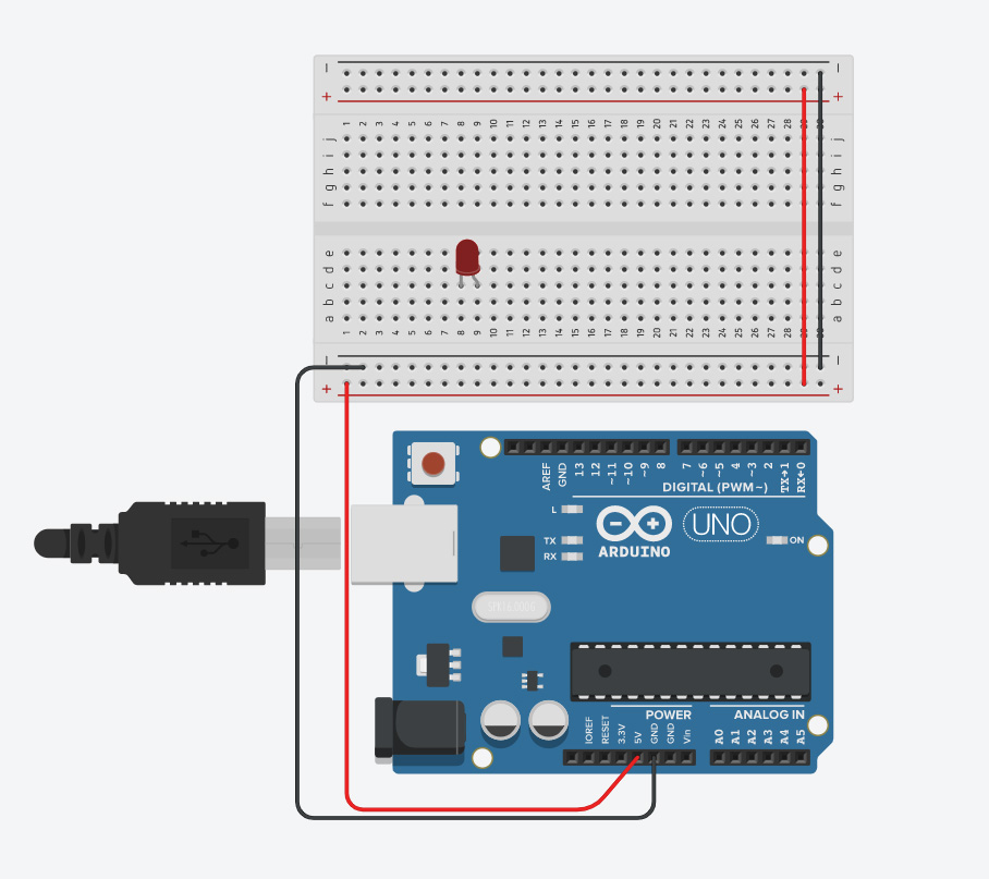
Now to wire it up. This virtual sim acts as if the Arduino is plugged into the computer, so we will not need to worry about a power source. Your power (marked with +) should be Red, and your ground (marked with –) should be Black. That way we know where it is coming and going from.
(Some shortcuts: 1-0 changes the wire colors. 1 is black, and 2 is red. Holding down Shift keeps them straight.)
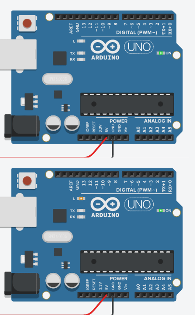
The power we want to use is 5V on the Arduino, and either GND will work as a ground. Adding the extra wire on the breadboard allows the power to spread across the whole board.
(You don’t need to stagger them like the example, but doing so helps if you need to troubleshoot.)
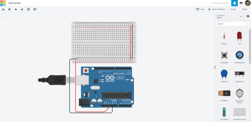
That’s a great start! But now we’re going to stop for now and hop back to the IDE.
Coding in the IDE:
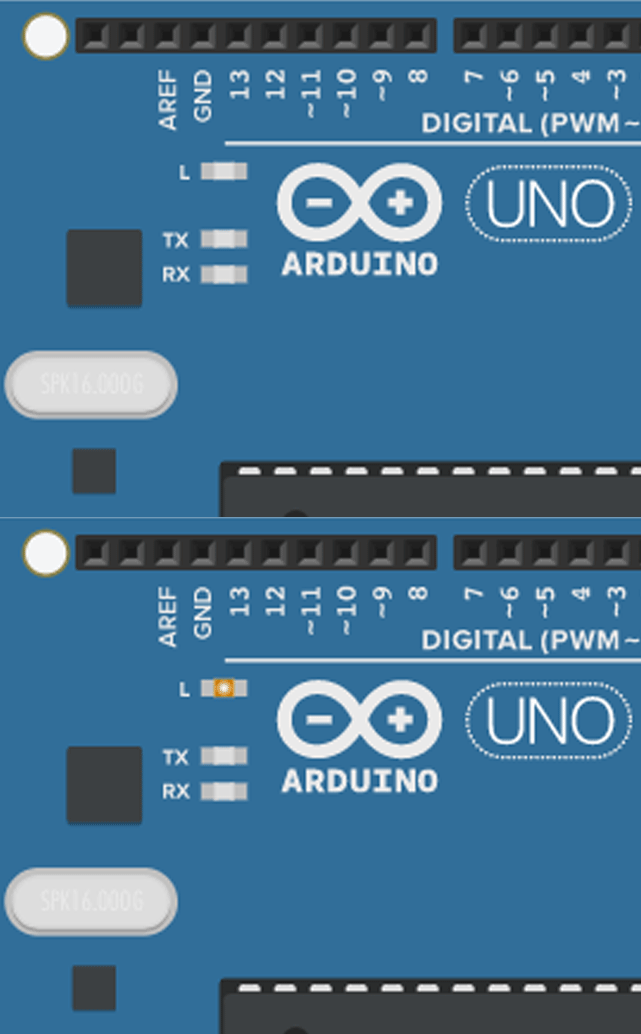
We’re going to run a test sketch, called Blink. This will make the LED built into the Arduino blink. In the physical space, this is how we test if the Arduinos are working properly.
Open up the Arduino IDE. Go to File > Examples > 01. Basics > Blink. It will open in a new window.
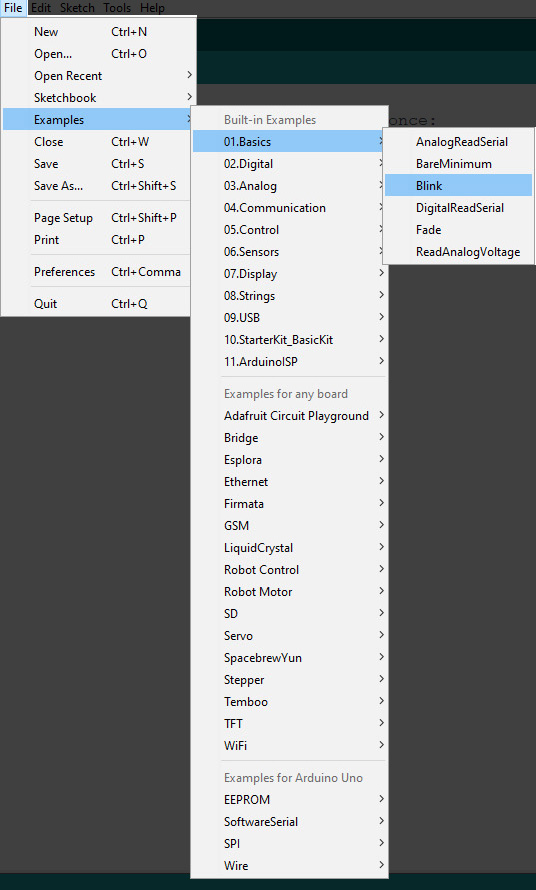
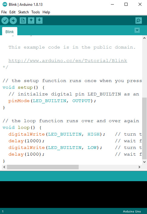
Or if you’d rather copy and paste here is the code below, with explanations of the code. Anything marked with // tells the Arduino and IDE to not read it as code. These are for comments, which help explain the code.
void setup() {
  // This is setting up actions that will happen when the board is powered.

  pinMode(LED_BUILTIN, OUTPUT);
// this is telling the Arduino that we are designating certain pins as outputs (where information goes out) or inputs (information goes in). LED_BUILTIN is a shortcut in the code for the LED built into the Arduino. OUTPUT means that the LED is an output; so information will be going out to it-- in this case the command to blink.

}

// Each function ends with a bracket.

void loop() {
// Here is establishing action(s) will continue to repeat on a loop so long as the Arduino is powered.

digitalWrite(LED_BUILTIN, HIGH);
// digitalWrite means it is sending information out to a digital pin so when the LED is on or HIGH, it will turn on

delay(1000);
 // wait for a second; Arduinos read time in milliseconds

digitalWrite(LED_BUILTIN, LOW);
// Send out the message to turn the LED off or LOW.

 delay(1000);
// wait for another second

}
//close the function with a bracket. As it is a loop and has no orders to stop, it will continue to do this until you turn it off or it loses power
Now it’s good practice to debug the code, even if you’ve never changed anything on this sketch. To do this, go to Sketch > Verify/Compile. You can also just clock the little checkmark on the upper left of the user interface, or Ctrl/Cmd +R
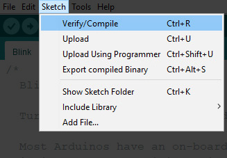

If you don’t have any orange text, you’re in the clear! If you do, then you’ll have to debug it. This shouldn’t happen if you have just opened the sketch fresh from installation.
Running the Simulation:
This is really easy. Go back to your circuit and select Code.
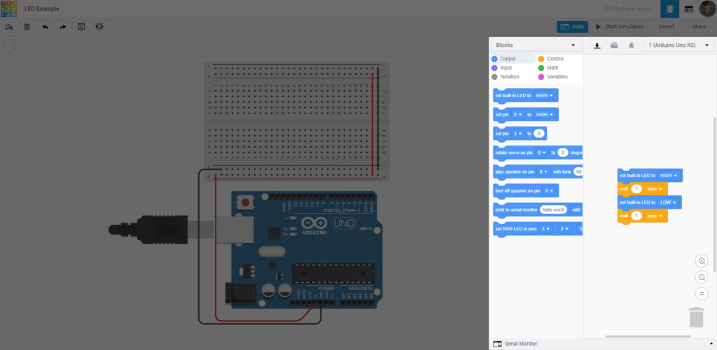
As you can see, it’s set to a set of blocks. This is another coding language called Scratch, but we don’t need it! Under the dropdown menu, select Text.
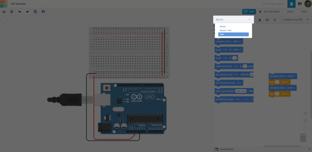
Select Continue on the warning– it’s just saying that the block code won’t be saved.
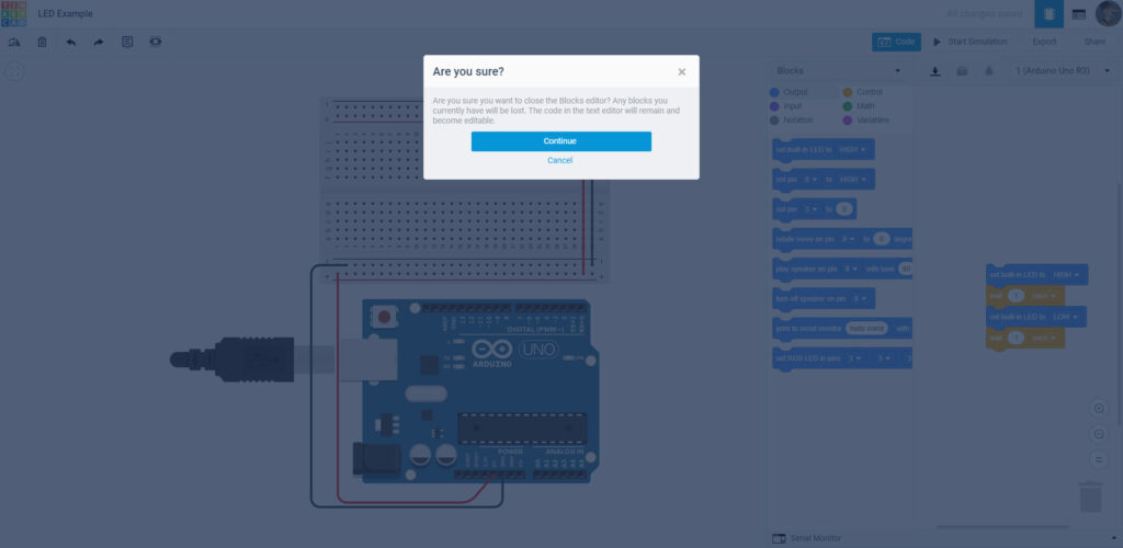
And here we are!
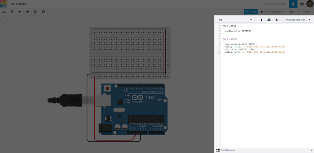
The neat thing about this is it will predict code based on the circuit. This might be great for this, but as we go on, we want to trust what’s in the IDE. For the sake of practice you can go to the IDE and copy the code and paste it into the Circuit Sim.
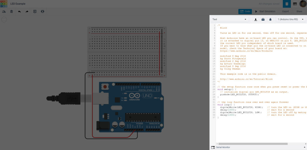
Since our code has been verified, go ahead and select Start Simulation. The little yellow LED on the Arduino should blink on and off if done right. (It’s very tiny so I don’t blame you if you don’t see it at first!)
LED Blink:
Now, we’re going to make an LED blink on the breadboard. Drag an LED from the Components List to the board. Feel free to use the dropdown menu to change the color. As you can see, there are two legs on the LED. One is the Anode (the bent leg) and the Cathode (the straight one with a flattish side). In real life, the anode is a longer leg than the cathode.
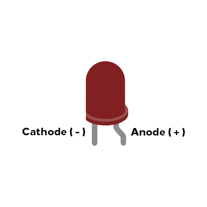
The anode is linked to the power side of the circuit and the cathode goes to the ground side. If you flip them they might get hot but not light up. It’s very important to know which is which when making a circuit.
Put the LED on your breadboard. Make sure each leg is in a different “row” of the board.
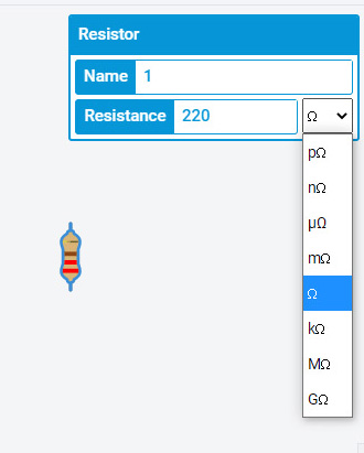
Next pull out a Resistor. Now resistors have different values, providing more or less resistance. These are measured in Ohms (Ω). To change it here, go into the dropbox and find the singular Ω symbol. Then in the box next to is put in 220. You will see the bands on the resistor changes.
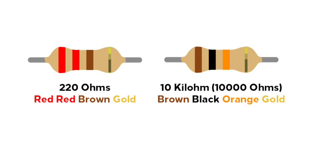
This is how you can tell what resistor is which resistance. If you want to learn more, you can read more HERE.
Now resistors don’t have a set “pole”, like the LED so you can put either end in either direction. You do have to place it on the same row on the breadboard as the anode (bent) leg. The other leg can go onto another row.
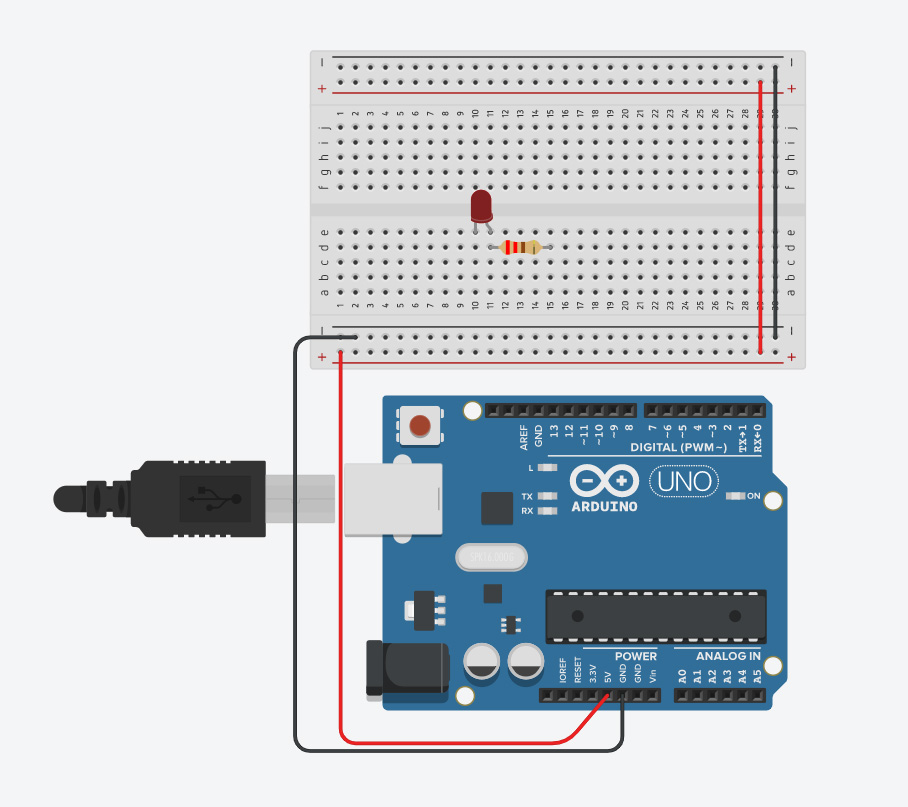
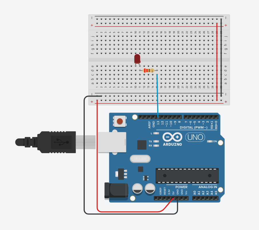
On the same row as the resistor leg away from the LED, click the hole below and guide it to Pin 13 on the Arduino. Make it blue with either the dropbox of hitting 7.
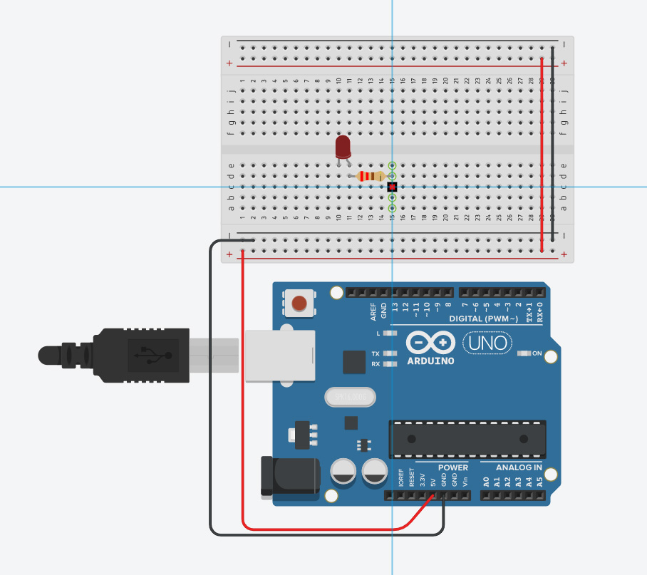
Click the hole below the cathode (straight leg)and make a black wire to the ground row on the breadboard (marked with a –).
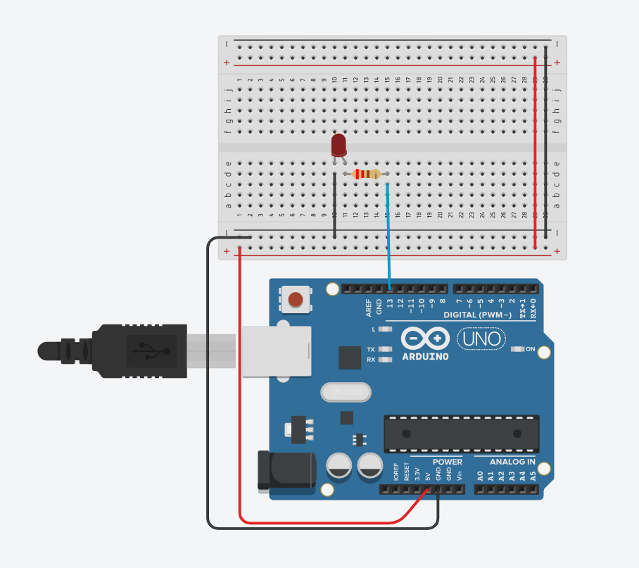
Then sun the simulator again. If you’ve wired it correctly, the LED on the breadboard and the Arduino should both be blinking.
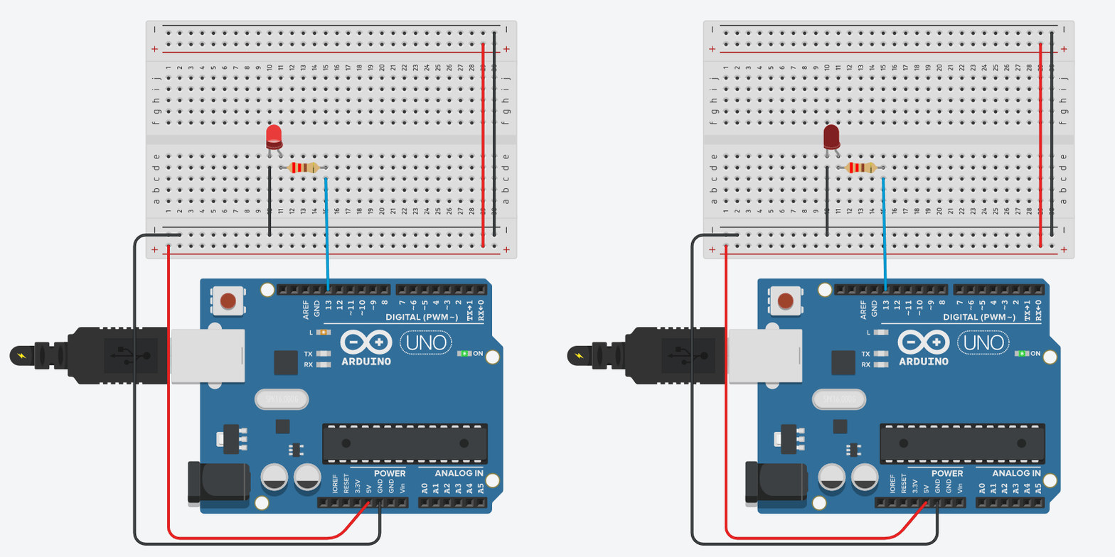
Pin 13 is always equated with the internal LED, so when you use that pin to light things up, chances are the LED will also turn on.
Now that we have the basics down, let’s go a little bit further.
LED and Button:
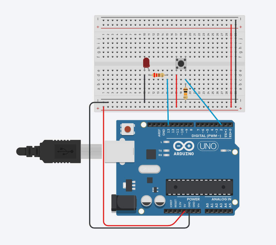
Drag a Pushbutton from the components window. Place it anywhere on the breadboard so long as it’s straddling the trench.
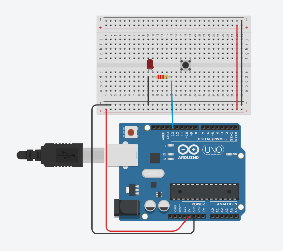
Drag out the second resistor, change the dropdown to kΩ and put 10 in the box. This should give you a 10k ohm resistor. Put one end into the ground row of the breadboard and the other in the same row as the bottom right leg of the pushbutton.
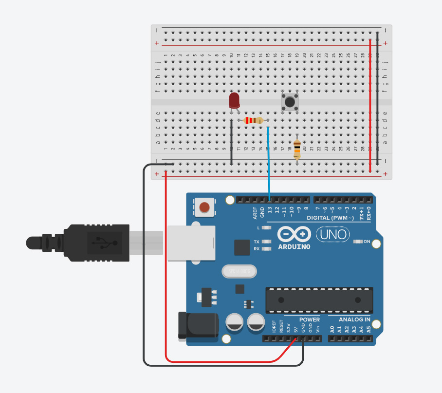
Underneath the bottom right leg of the button, make another blue wire and place it into Pin 2 on the Arduino.
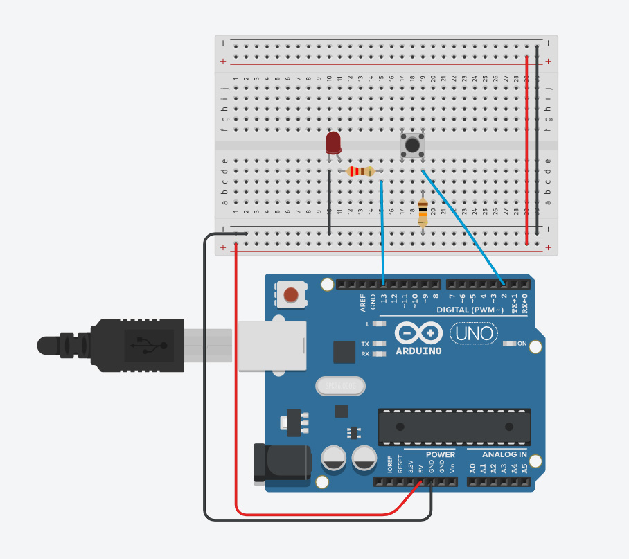
Underneath the bottom left leg of the button, make a red wire connecting to the power row on the breadboard.
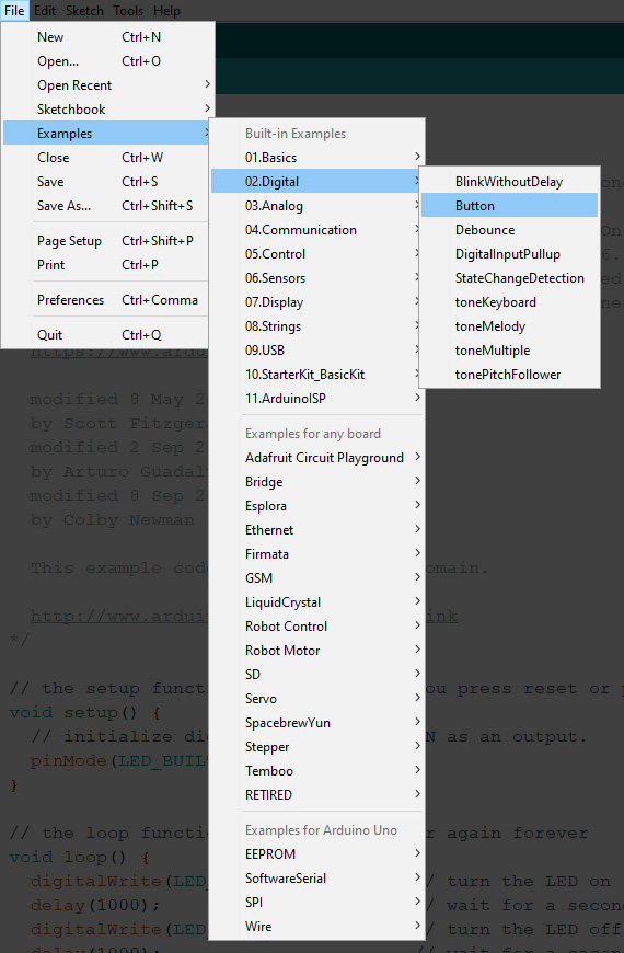
Now back to the code! In the Arduino IDE go to File > Examples > 02. Digital > Button.
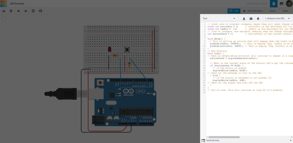
As you can see, the code has changed and we have things outside of the void setup().
// const ints or constant integers, means they will never change no matter what. These are set outside the functions as universal variables that can be used anywhere in the code

const int buttonPin = 2;
// buttonPin is the shorthand for our button on Pin 2.

const int ledPin =  13;
// ledPin is the shorthand for our LED on Pin 13.

// ints or integers, are variable, meaning they can change throughout the code.

int buttonState = 0;
// buttonState is the current status of button. It defaults to 0, which means the button is off.

void setup() {
 // This is setting up actions that will happen when the board is powered.

pinMode(ledPin, OUTPUT);
// This is saying “hey, ledPin is an output, so send information out from there”

  pinMode(buttonPin, INPUT);
// This is saying “hey, buttPin is an input, so get information from here”

}
// End function

void loop() {
// Here is establishing action(s) will continue to repeat on a loop so long as the Arduino is powered.

buttonState = digitalRead(buttonPin);

// Asking what is the current state of the button? And reading the information from the buttonPin.

if (buttonState == HIGH) {
// if the button is pushed

digitalWrite(ledPin, HIGH);
// Send out the message to turn on the LED

} else {
// if the button is released or not pushed (0)

digitalWrite(ledPin, LOW);
// Send out the signal and turn off the LED

}
}
// End of code. This will continue so long as it’s powered.
Verify your code id you’re using the IDE, and copy and paste it into the code box on the Circuit Sim.
Run simulation. When you click the button with your mouse, both LEDs should turn on.
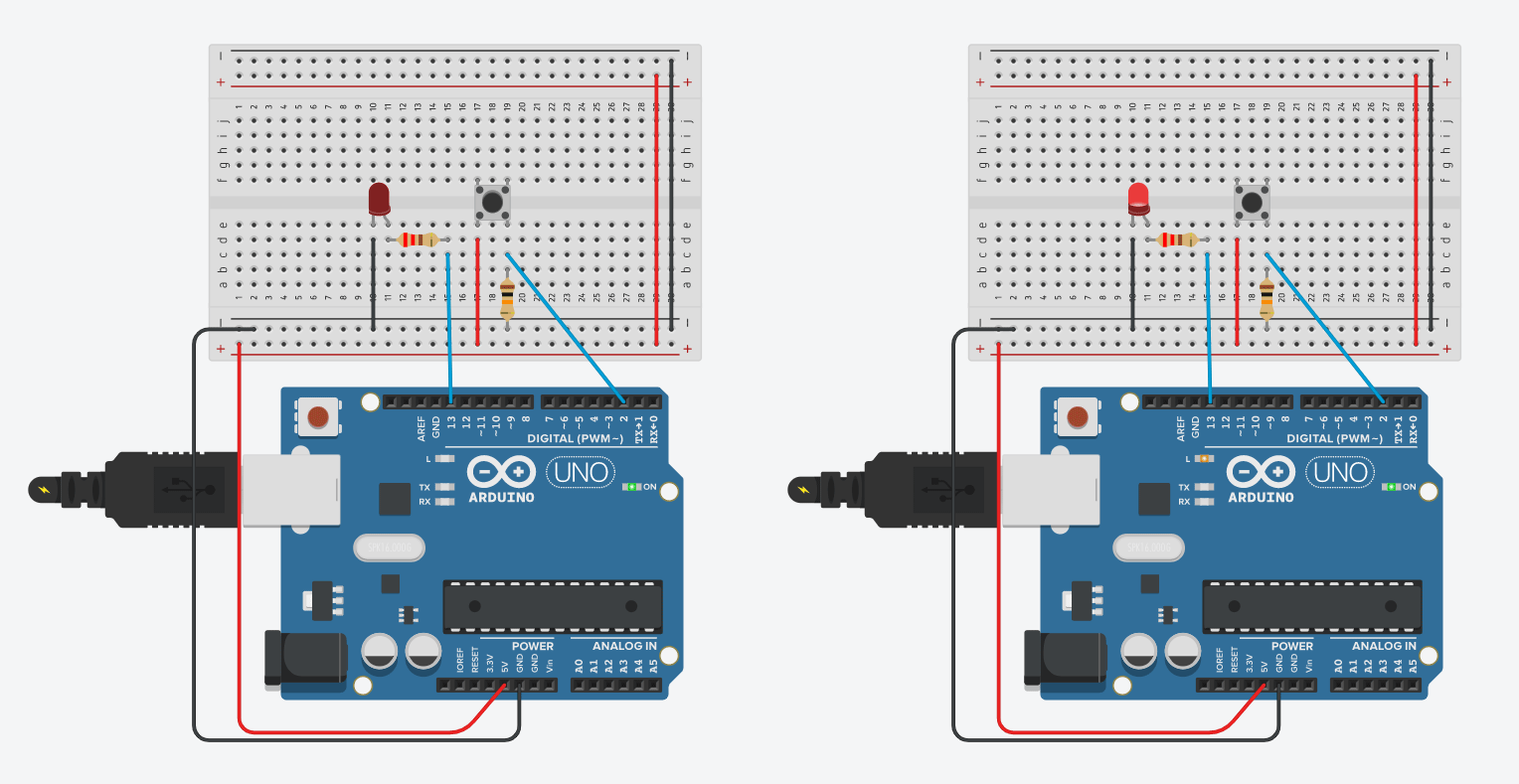
Now we’ve got two circuits under our belt. But there’s one more to go!
LED and Potentiometer:
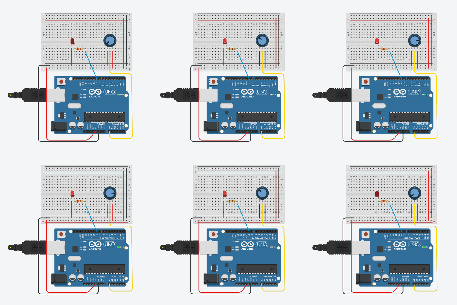
Back to the circuit! Remove everything but the LED and the 220 ohm resistor. Move your blue wire from Pin 13 to Pin 9.
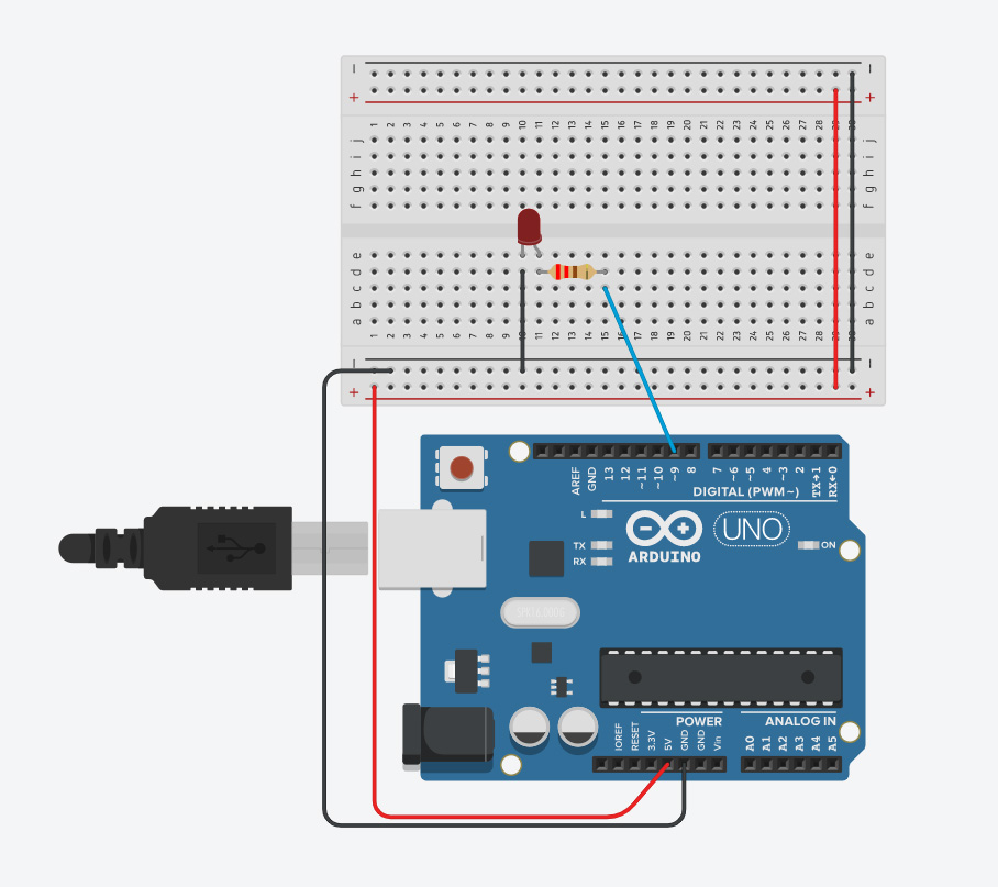
Drag a Potentiometer from the components list. Make sure the dropdown box is set to kΩ and the box set to 10— making it 10 kΩ.
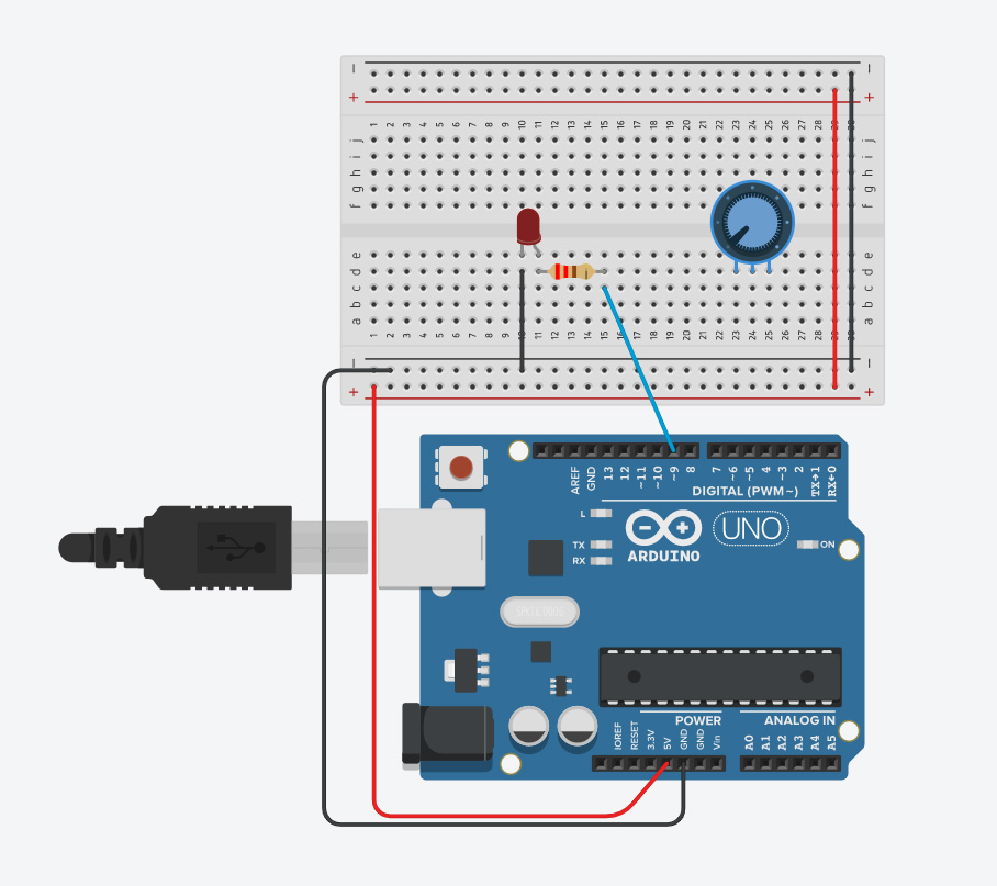
Under the furthest right pin, make a red wire connecting to the power row on the breadboard.
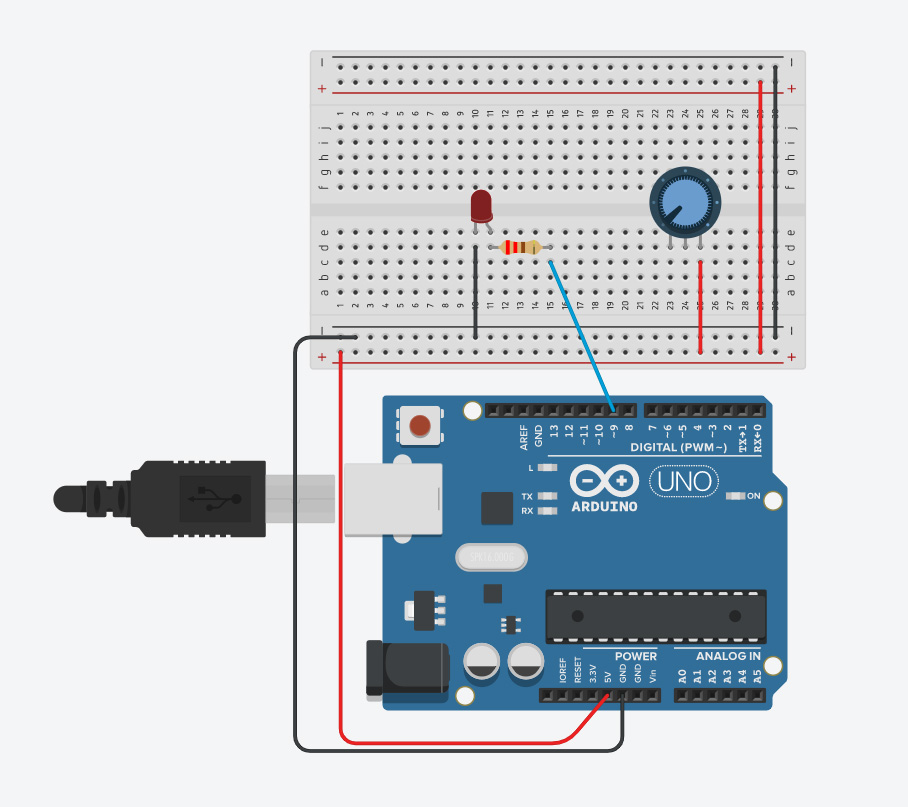
Make a black wire from the furthest left to the ground row of the breadboard.
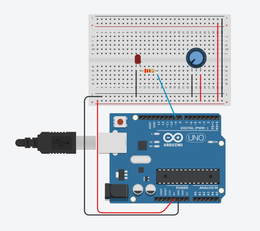
Make a yellow wire (4) from the center pin and lead it to the pin A0.
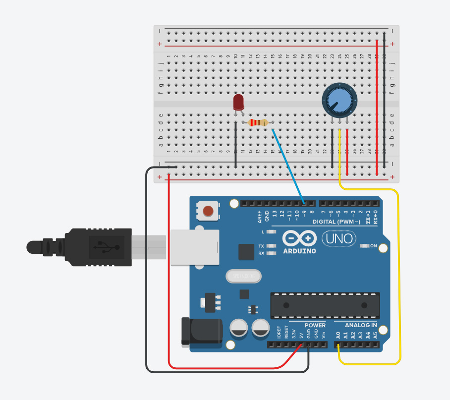
These are Analog Pins, which can take a wider range of signals compared to the Digital Pins we’ve been using so far. Digital pins only take a digital signal, which is binary; so HIGH/LOW or On/Off. Which is what we want, as the potentiometer is just a fancy name for a dial which can be turned on increments as opposed to the on and off of a button.
Once more again, back to IDE. Go to File > Examples > 03. Analog > AnalogInOutSerial.
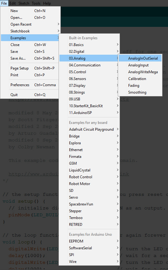
Once again you can also copy the code here as I break it down.
const int analogInPin = A0;
// This is the shorthand for our Analog input, set to Pin A0.

const int analogOutPin = 9;
// This is the shorthand for our output, which is the LED set to Pin 9.

int sensorValue = 0;
// The value read from the potentiometer, set to 0 as a default.
int outputValue = 0;
// The value being sent out to LED; the larger the number the brighter the LED will be. Set to 0 as a default

void setup() {

Serial.begin(9600);
// Start a serial communication in the Arduino at 9600 bits a second
}

void loop() {

sensorValue = analogRead(analogInPin);
// Reads the information from the potentiometer

outputValue = map(sensorValue, 0, 1023, 0, 255);
// Take the information read from the potentiometer and map it to value that is equal the brightness of the LED.

analogWrite(analogOutPin, outputValue);
// print the results  of the readings to the Serial Monitor

Serial.print("sensor = ");
// prints “sensor =” in the Serial Monitor

Serial.print(sensorValue);
//prints the sensor value in the Serial Monitor

Serial.print("\t output = ");
//prints “output=” in a second row in the Serial Monitor

Serial.println(outputValue);
//prints the output value in the Serial Monitor

  delay(2);  //Have a 2 millisecond pause between each reading

}
//Code end
Verify the code in the IDE and move back to circuit sim.
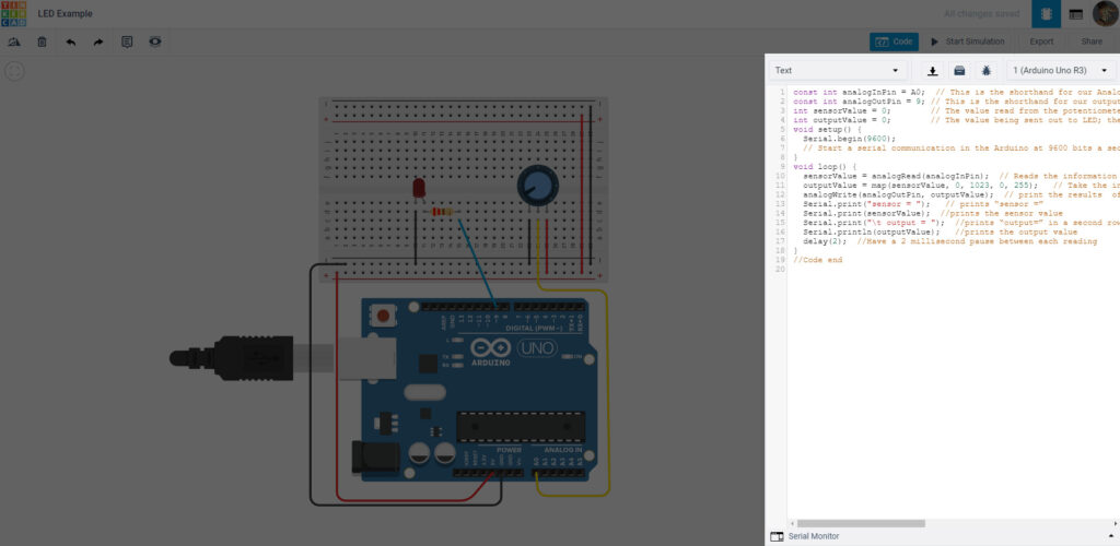
If you notice on the bottom there’s something called the Serial Monitor. As you saw in the code, it prints out values so you can see them. This is good for gathering data or troubleshooting your sensors in the physical space. Open that up and run the simulation. If you’ve set it up right you should be getting a rapid set of strings as you turn the potentiometer.
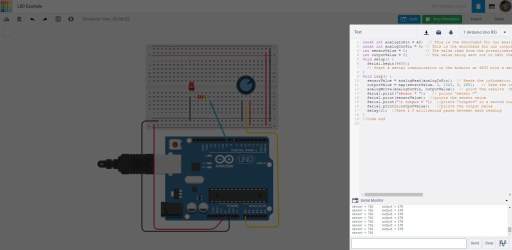
You may also notice the LED going bright and dim as you turn the knob.
Congratulations! You’ve touched some basics of physical computing– virtually. We encourage you to explore further with different circuits and different components.
Keyboard Shortcuts:
- Z Recenter project
- S Start/Stop Simulation
- E or Num 5 Open/closes Code Editor
- C or Num 3 Open/closes Components
- Shift Hold and drag with the mouse to select and move multiple objects; by default everything will move.
- Ctrl/Cmd + C Copy
- Ctrl/Cmd + V Paste
- Ctrl/Cmd + Z Undo
- Ctrl/Cmd + Y Redo
- Ctrl/Cmd + + Zoom In
- Ctrl/Cmd + – Zoom Out
- Backspace or Delete Delete object
- R or F3 Rotate Object(s) Clockwise
- Shift + R or Shift + F3 Rotate Object(s) Counter Clockwise
- 1 – 0 Change the selected wire color during drawing
- Esc Deselect Object(s)
- Left / Right / Up / Down Arrows Moves selected object(s) by a large increment
- Shift + Left / Right / Up / Down Arrows Moves selected object(s) by a small increment
Further Exploration:
- (Virtual) Physical Computing Slideshow
- Getting Started with Arduino
- Introduction to Arduino on Arduino to go
- Physical Computing page at ITP NYU
- “Massimo Banzi: How Arduino is open-Sourcing imagination”
- Physical Computing Projects on Adafruit
- Sparkfun’s Adventures in Science YouTube Playlist
- Jeff Feddersen’s Videos on Physical Computing & Electricity
- All About Circuits
- Resistor Code Calculator
- Ohm’s Law Calculator
- Electrical Symbols Guide (For Datasheets and Schematics)
- Reading a Schematic
