
We will learn how to build circuits and how to program an Arduino microcontroller.
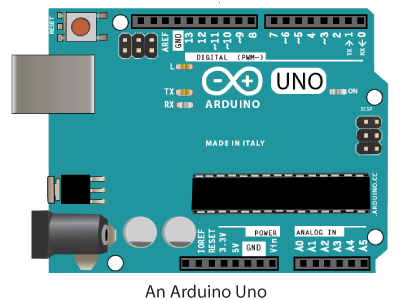
FIRST LOOK AT A MICROCONTROLLER: THE ARDUINO UNO
A microcontroller is a small computer that can take in information from inputs such as sensors and switches and control outputs such as lights, motors and other computers. Microcontrollers are widely used in many different ways; DIY and robotics, art installations, industrial applications, and the internet of things.
When you are using a microcontroller, or in our case a microcontroller platform, there are two components: hardware and software. The hardware includes the microcontroller and its input and output pins, and any input or output devices you want to attach to it. The software is programs you write that control the microcontroller and the devices you have attached to it.
We will be using the Arduino microcontroller platform. It was developed by a team of teachers to help their design students who were not engineers create physical interfaces. There are many different Arduinos, and clones as well. We will be using the Uno.
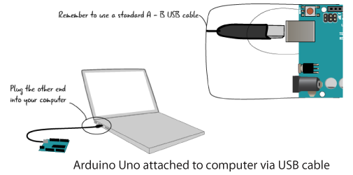
ATTACH AN ARDUINO TO A COMPUTER
To do this, you will need a computer, and Arduino Uno and a USB cable. The Arduino Uno
uses a USB A-B cable, while some clones of the Arduino use a USB micro cable.
LAUNCH THE ARDUINO SOFTWARE
The laptops in the Makerspace have the Arduino software, or IDE (integrated development environment) installed. An IDE, or integrated development environment, is a software application that allows you to write code and test that code out in the programming language the IDE supports.
If you are using your own computer, you can download the Arduino IDE here. The software is open-source and distributed free of charge.
The procedure for downloading and installing the software is slightly different for Macs and Windows. Detailed instructions for both platforms are here.
SETTING UP THE SOFTWARE
Before we start programming the Arduino, we have to set a couple of settings in the software to ensure that the Arduino can communicate with the computer.
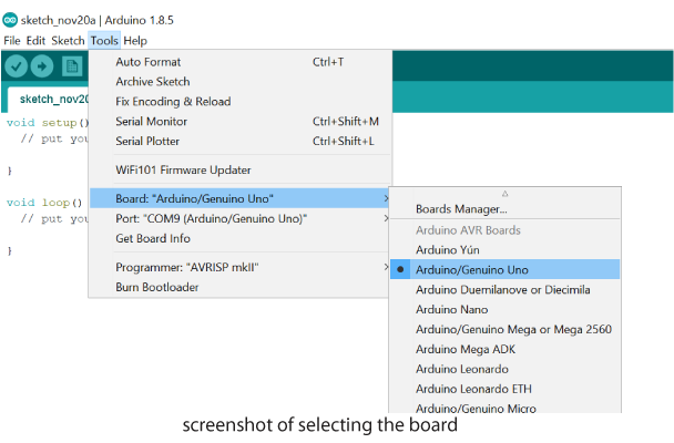
Launch the Arduino software. Once it is loaded, go to the Tools menu, select Board. From the fly out menu, select Arduino/Genuino Uno.
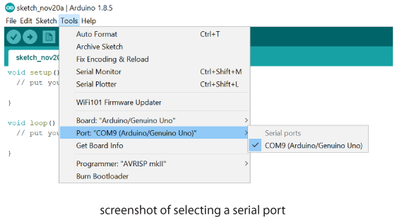
Next, it is necessary to specify a Serial Port for your Arduino to communicate with the computer. A Port is a channel of communication which connects your Arduino and the computer. On a Windows machine, go to the Tools Menu, select Port then select the COM port that is specified. It should look something like the screenshot below.
PROGRAMMING THE ARDUINO
The Arduino team has designed an IDE for use with their devices that has the features you need. It has a built-in code editor, which is a program used to write the code files that you create when programming. You can test your code in the IDE and solve problems with the help of a message area that shows errors in your code and a console that provides more detail about the nature of these errors. It has buttons so you can check your code, save it, create a new code window, upload it to your Arduino and more. The basic unit of Arduino programming is called a Sketch.
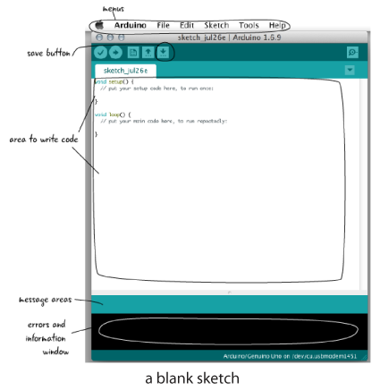
LOAD A SKETCH AND SAVE AS
With the Arduino IDE open, go to the File Menu > Examples > 01.Basics > Blink. This will open up the Blink Sketch. It’s always a good idea to save a sketch with a new name, you don’t want to write over the example sketch. Save it as Blink_2, for example.

VERIFY AND UPLOAD BLINK SKETCH
Once you have saved the sketch, click the Verify button to make sure it is ok. While it is highly unlikely anything would be wrong when you are loading a copy of one of the example files, it’s good to be in the habit of checking. After you verify, click the Upload button. This will load your code on to the Arduino board.

You will see an LED that is located near Pin 13 on the Arduino board blink on and off. What if it doesn’t? Check to make sure your Arduino is plugged into the computer. Check to make sure you have set the correct Board and Port settings.
BUILDING A CIRCUIT: THE BREADBOARD
Let’s build a circuit so we can blink an LED that is NOT built into our Arduino. Meet the breadboard. Breadboards were developed to make it easy to quickly prototype circuits without soldering components together. They have rows and columns of connected holes that allow us to attach our components to each other.

CONNECT THE UNO TO THE BREADBOARD
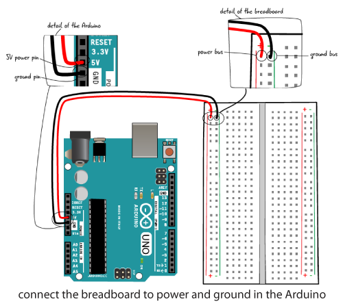
Make sure your Arduino is not plugged in to the computer. Whenever you are making changes to a circuit, your Arduino should NOT be plugged in.
Grab a couple of jumper wires. You are going to connect the Arduino to the breadboard. It is a convention to use RED for power and BLACK for ground. Put one end of the black wire into one of the pins marked GND on the Arduino and the red wire into the pin marked 5V on the Arduino.
Put the other end of the BLACK wire into the ground bus on the breadboard. It probably has a green or blue minus (-) sign near it. The other end of the RED wire goes into the power bus on the breadboard, which has a red plus (+) sign above it.
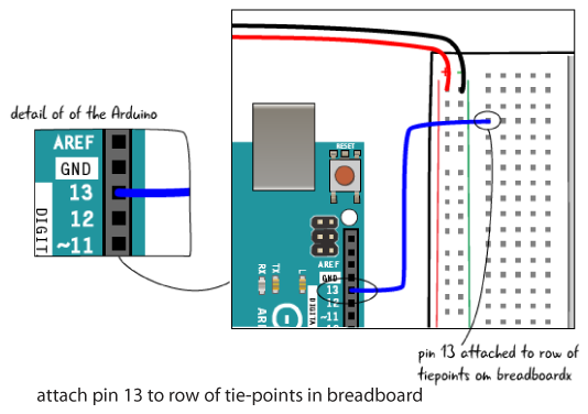
ATTACH PIN 13 TO THE BREADBOARD
Grab a jumper and attach PIN 13 to a row of tie-points in the breadboard.
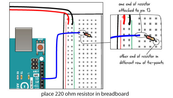
ADD A 220 OHM RESISTOR
Place one end of a 220 Ohm resistor in the same row of tie-points as the jumper from pin 13, and the other end in a different row of tie-points.
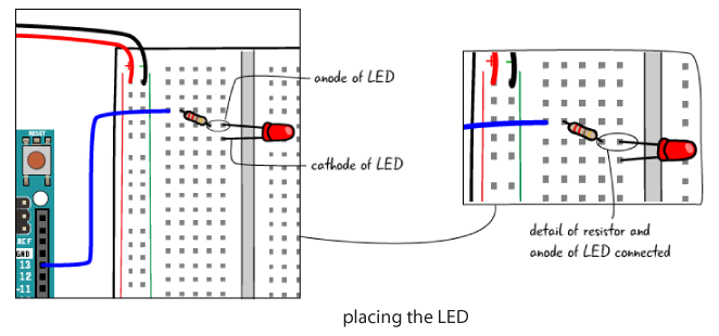
ADD THE LED
Now let’s add an LED to the breadboard.
An LED (light emitting diode) has an orientation, or a positive and negative lead. An LED must be placed into a circuit properly, with the positive and negative lead oriented properly. How do you know what is the positive and negative side? The positive side has a longer lead. It is called the anode. The negative lead is shorter and called the cathode. Also, the negative side of an LED often has a flatter side at the bulb.

Place the anode (long end) of the resistor in the same row of tie-points as one end of the resistor, and the cathode (short end) into another row.
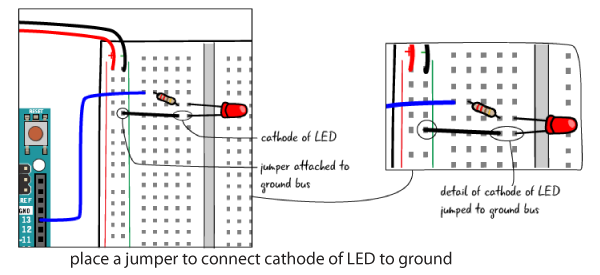
JUMP THE CIRCUIT BACK TO GROUND
The final step to complete the circuit is to attach a jumper from the cathode of the LED to the ground bus on the breadboard
PLUG IT IN AND RUN BLINK
You’ve completed the circuit! If you plug the Uno back into your computer, the LED should be blinking. Why does it run when we haven’t changed the code?
And what if it isn’t blinking? Carefully check all the connections you have made with the components and jumpers.
ADD A BUTTON
Let’s make this circuit more interactive and add a button. We will leave the LED, resistor and buttons right where they are. Be sure to unplug the Arduino from the computer before you make changes!
Place a momentary switch over the trench in the bottom of the breadboard. The button’s pins should be placed so there are two pins on either side of the trench.

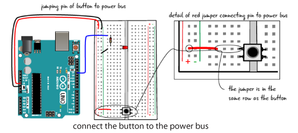
CONNECT BUTTON TO POWER BUS
Add a jumper that connects the power bus to one side of the button.
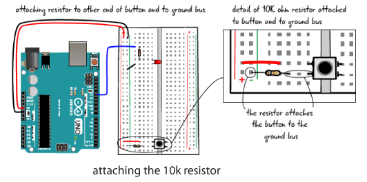
ADD A 10K RESISTOR
Place a 10K resistor in the breadboard, with one end in the ground bus and the other end attached to the other pin of the button.
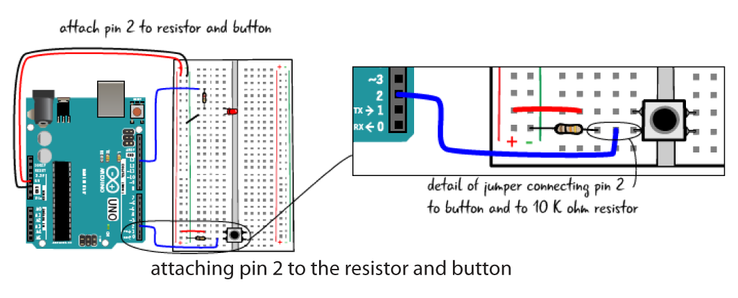
ATTACH PIN 2 TO BUTTON AND RESISTOR
Place one end of a jumper in pin 2 and the other end in the same row of tie-points as the 10k resistor and one of the pins of the button.
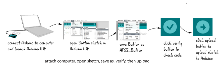
You’ve completed the circuit. Now attach the Arduino to your computer. In the Arduino IDE, open from the File Menu > Examples > 02.Digital > Button. Save as, with a name like MyButton.
Now when you press the button, the LED will light up. If it doesn’t, carefully check all of your connections.
ANALOG INPUT AND OUTPUT
We’ve learned how to turn something on or off with a button, but sometimes you want more. How about controlling the brightness of the LED? Let’s learn how to use analog input and output. We will use a potentiometer.
A potentiometer, sometimes called a pot, is a knob or dial that can be turned to increase or decrease the amount of resistance depending on how far, and in which direction, it is turned. Potentiometers come in many sizes and shapes. We will be using a 10k ohm potentiometer in our circuit.

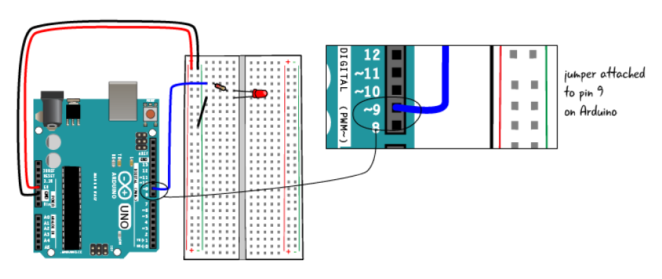
MOVE THE JUMPER TO PIN 9
We will start with the same basic circuit. If you still have the button in the breadboard, remove it as well as the jumpers and resistor. Also, move the jumper attached to the resistor from Pin 13 to Pin 9.
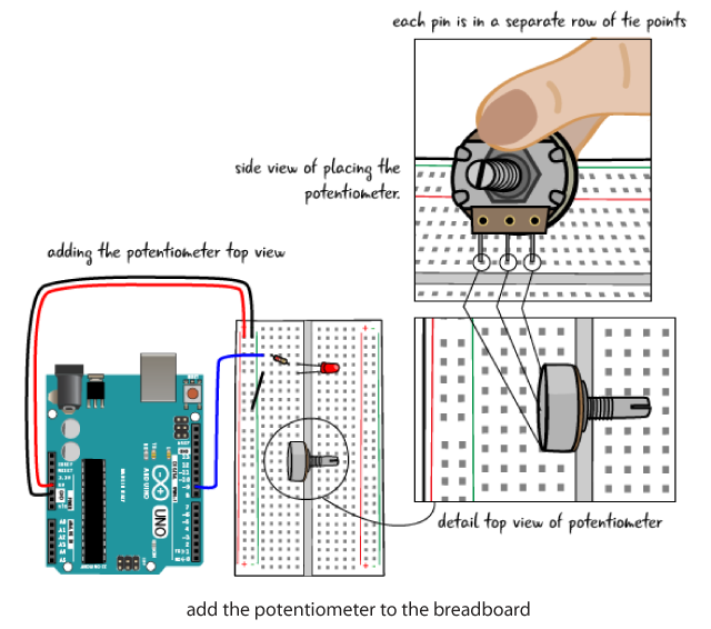
ADD THE POTENTIOMETER
We will place the potentiometer parallel to the trench as depicted in the drawing. Each pin of the potentiometer is in a separate row of tie points, with an empty tie point between each of the pins.
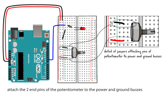
CONNECT THE POTENTIOMETER TO POWER AND GROUND
With a jumper,, attach the pin at one end of the potentiometer to the power bus. Attach the pin at the other end of the potentiometer to the ground bus.
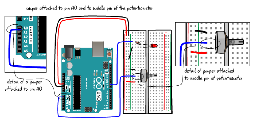
ATTACH THE MIDDLE PIN OF THE POT TO PIN A0
Finally, attach the middle pin of the potentiometer to Pin A0, which is on the other side of the Arduino Uno as shown in the drawing.
ATTACH YOUR COMPUTER AND UPLOAD THE SKETCH
After connecting your computer to the Arduino, in the IDE, navigate to File Menu > Examples > 03.Analog > AnalogInOutSerial. You might want to Save As, MyAnalogInOutSerial, for example.
Now when you turn the potentiometer, your LED should have a full range of brightness, from unlit to fully bright.
You are curious about learning more about circuits and the Arduino, you can visit our page on Physical Computing for more information and links.