Creating a 3D Model in Tinkercad
Your model can be built from shapes, text or a combination.
CREATE AN ACCOUNT IN TINKERCAD
Tinkercad is a free web-based 3D modeling program. You must create an account to work with it.
Here’s how to make an account:
On the upper right corner of the main site, click JOIN NOW.

Next, select Create a Personal Account

Select Sign Up with Email

Select your country, and your birthdate, then hit NEXT.

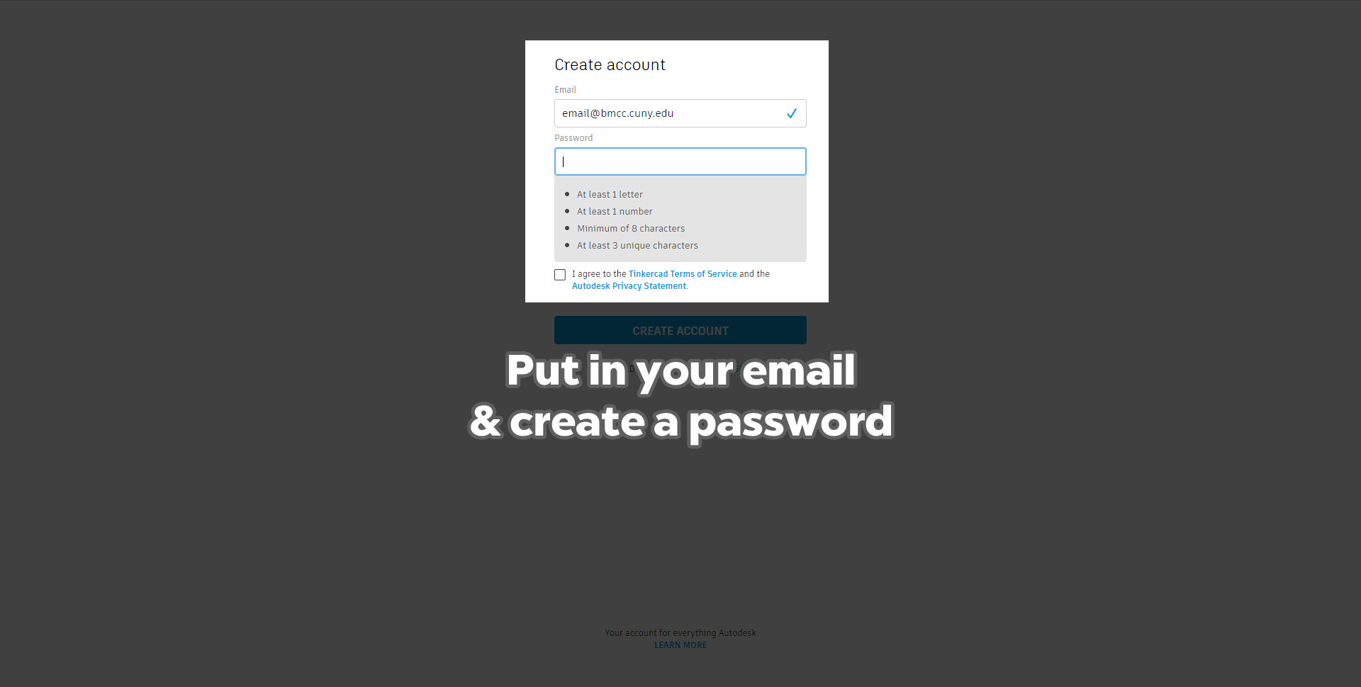
Put in the email you wish to use and a password. It needs to be a minimum of 8 characters, at least 1 letter and 1 number, and at least 3 unique characters.
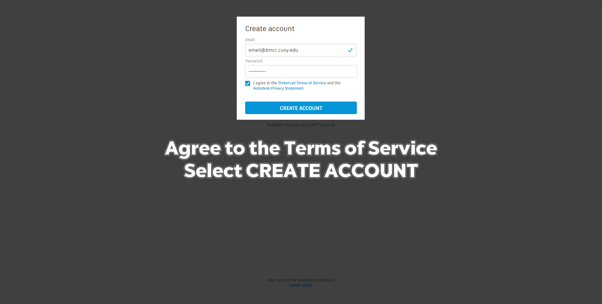
Click the box to agree to Autodesk’s Terms of Service, then select CREATE ACCOUNT
They will take you to their own tutorial, but skip it for now. You can revisit theirs later.
Now create a new file. Here’s a screenshot of the interface:
 The workplane is where you will create your models. On the left are a series of icons that allow you to change your view of the workplane. On the right is a menu that is filled with shapes you can use to create your models.
NAVIGATING THE TINKERCAD INTERFACE WITH A MOUSE
A couple of things before we get started:
There are a number of ways to navigate the Tinkercad interface. It is much easier to work in any 3D software with a mouse.
- To rotate the workplane, right click and hold to get different views.
- To pan the workplane, hold down the scroll wheel
- To zoom in or out, use the scroll wheel.
- Keep your models small!
- Don’t have any large overhangs in your model! There should not be any angles greater than at most 45 degrees from the workplane. We will explain this more as we work through this.
NAVIGATING WITH THE VIEW CUBE AND NAVIGATION MENU
- By clicking the sides of the view cube, you can navigate to
left, right, top bottom and front views of the workplane. The view cube will rotate to reflect the position you have chosen whatever means you are using to navigate. - Click the home button to get the standard view.
- Fit all in view shows all of the objects on the work plane.
- Fit view to selection shows whatever object you have selected.
- + zooms in.
- – zooms out.
 EDITING THE GRID
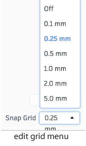
In order to have more precise control over your model, edit the grid of the workplane from 1.0 mm to 0.25.
This menu is in the lower right hand corner of the workplane.
DRAG A SHAPE TO THE WORKPLANE
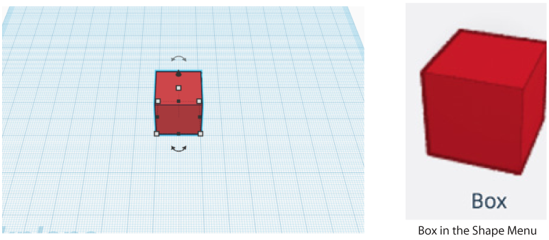
Let’s start with a Box. Click on a box in the Shape Menu and drag it to the workplane.
MOVE YOUR SHAPE
When you move an object in 3D space without rotating or scaling it, that is called translation.
- Moving an object left to right is translating it along the X axis.
- Moving an object front to back is translating it along the Y axis.
- Moving an object up or down on the workplane is translating it along the Z axis.
When you drag a shape in the workplane, you will see the numbers that indicate how far you have translated the shape, in millimeters. You can click on the shape to select it, then drag it forward, backward, to the left or right.
If you want to move an object up or down, click on the black arrow at the top of a shape when it is selected. You can move it above or below the workplane.

SCALE YOUR SHAPE
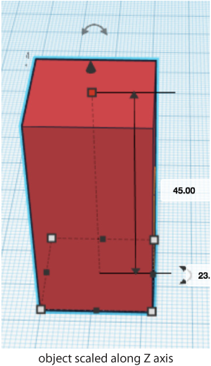
When an object is selected, you see 5 white squares and
4 black squares arranged around the object. These are
the scaling handles.
Move the cursor over them. If the cursor is over a black handle, you see the dimensions of the object along the X or Y axis. If you put the cursor over a white handle, you see the dimensions for both the X and Y axes, The white handles scale in 2 dimensions, the black handles scale on one axis. Put the cursor over the white handle at the top, and you will see the dimension for the Z axis.
Click on the white handle at the top and scale your object up and down. Try clicking on the black handles and scale up and down.
ROTATING AN OBJECT
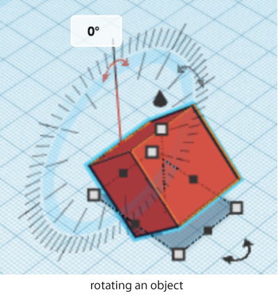
You can rotate an object around its 3 axes: X, Y and Z. When an object is selected, you can see the rotation handles for these axes. If you move over the handles with the cursor, you will see the rotation protractor, showing you the possible degrees of rotation for that axis.
The Z axis is perpendicular to the workplane, it is relatively intuitive to rotate on that plane. The X and Y axes can be more confusing. Rotating along the X axis rotates a shape left-right. Rotating along the Y axis rotates an object front-back. If the cursor is placed inside of the protractor, the shape will be rotating by 22.5 degrees. If the cursor is outside of the protractor, the shape will be rotated by 1 degree.
Try rotating the shapes in all three axes.
DUPLICATING AN OBJECT
There are many ways to duplicate a shape in Tinkercad. One of the simplest is to select an object, hold the alt key on Windows or the option key on a Mac, and drag.
You can also click the Duplicate Icon at the top left of the interface.
In the screenshot below, the box has been scaled, rotated and duplicated.

GROUPING OBJECTS
Most objects are made of a combination of shapes joined together. Let’s combine the scaled and rotated boxes.
First select them both, by clicking and dragging, or by shift clicking both objects. Then click on the Group Icon in the upper right hand menu in the interface (see above). The shapes have been combined and are now one object.


ALIGNING SHAPES
Let’s align some shapes.
In the example, letters are dragged from the text and numbers menu that is toggled in with Basic Shapes.
Select all three objects, then click the Align Icon in the upper right hand menu.
You will now see dots or handles around the selected objects that indicate how you might want to align your objects. There are handles on the X, Y and Z axis. You will see a preview of what it will look like when you click the handles when you roll over the handles.
When you click on the handle, the shapes will align along that axis.

Play around, create a design you like. Remember that you will not be able to print a model that has an overhang, and that you should keep your model small.
A good size to shoot for in this case is no bigger than 40 or 50mm on the X and Y axis, and 5mm on Z, or height.
CHECK SIZE
To check the size of your model, drag a ruler from the menu on the upper
right of the interface.

MAKE SURE YOU HAVE A HOLE
If you are making a keychain or a charm, that is.
You can add a cylinder hole through your model and group it.
You can also attach a tube, scale it and group it, as shown in the screenshots below.

Before you complete your model, make sure you look at it from all of the sides so you know what you are going to print to avoid unpleasant surprises!
NAME YOUR MODEL
Make sure you name your model with your first and last name.
EXPORT AS STL
When you have completed your model, click the button marked Export in the upper left corner of the interface.
- Include Everything in the design
- Select the option For 3D print .STL

We will be distributing flash drives to collect all of your models/STL files.
In order to print your models, they will need a further step, to be sliced into layers and described in a language (g-code) the printer understands.
We have 2 different types of printers in the Makerspace, so we will do this step. Check out the handout that explains this process for our Ultimaker printers, we have copies available in the Makerspace.
