What is digital Fabrication?
Digital fabrication refers to the production of objects with machines that are controlled by a computer. A digital file is created and sent to the machine to be printed, cut etc.
The first computer-controlled milling machine was created at MIT in 1952, but digital fabrication tools have seen a huge rise in popularity and performance since the early 2000s, thanks to better software, hardware and lower costs.
The term “digital fabrication” encompasses a wide range of materials and objects, including toys, furniture, medical equipment, clothes…even bridges and houses! Here are some important digital fabrication tools you should be familiar with (they can all vary greatly in size and performance within each category – from consumer/desktop size to industrial settings):
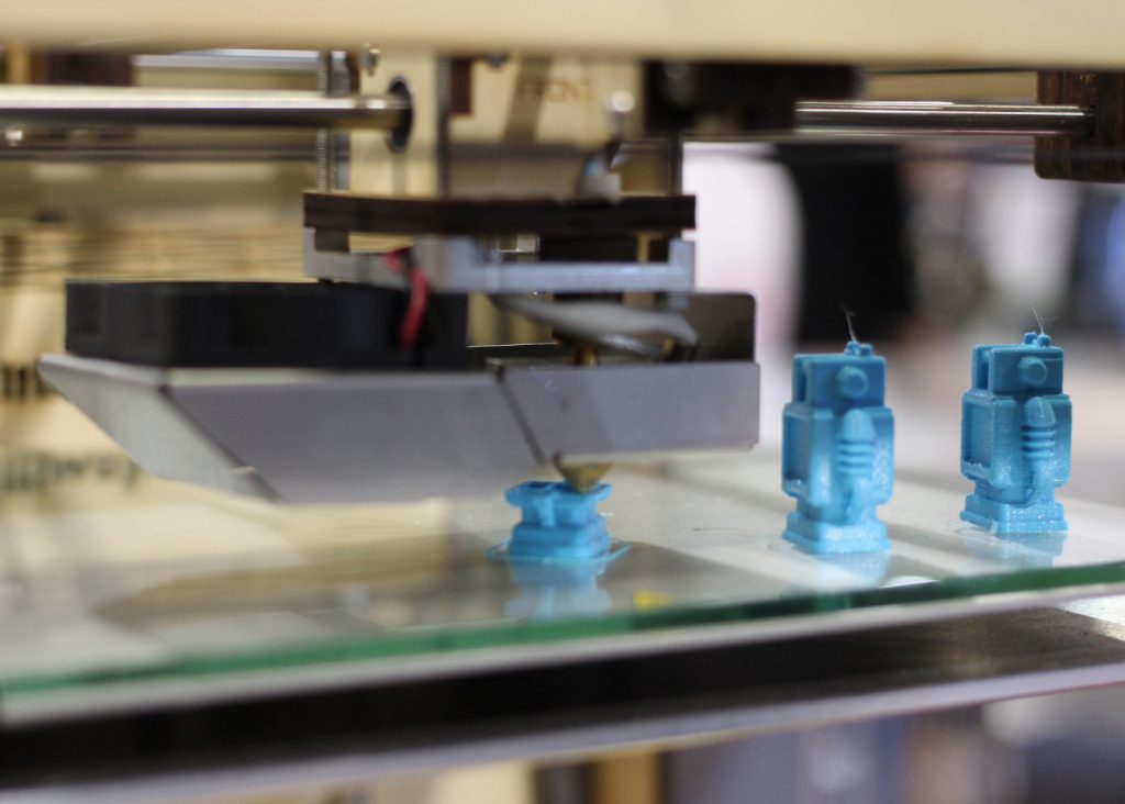
3D printing: The objects are modeled in a 3D modeling software (i.e: Tinkercad, Maya, Cinema 4D) and built up out of layers of PLA (a type of plastic) or resin. Each layer is very thin and the printing process can be quite long depending on the size and resolution of the object.
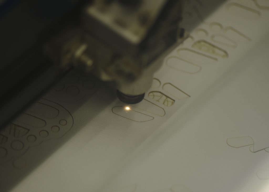
Laser cutting: A sheet of acrylic, wood, fabric or metal is laid on the laser cutter’s flat bed and is cut or engraved with a very precise laser beam. The depth of the cut is based on the speed of the laser beam (the slower the speed, the deeper the cut).
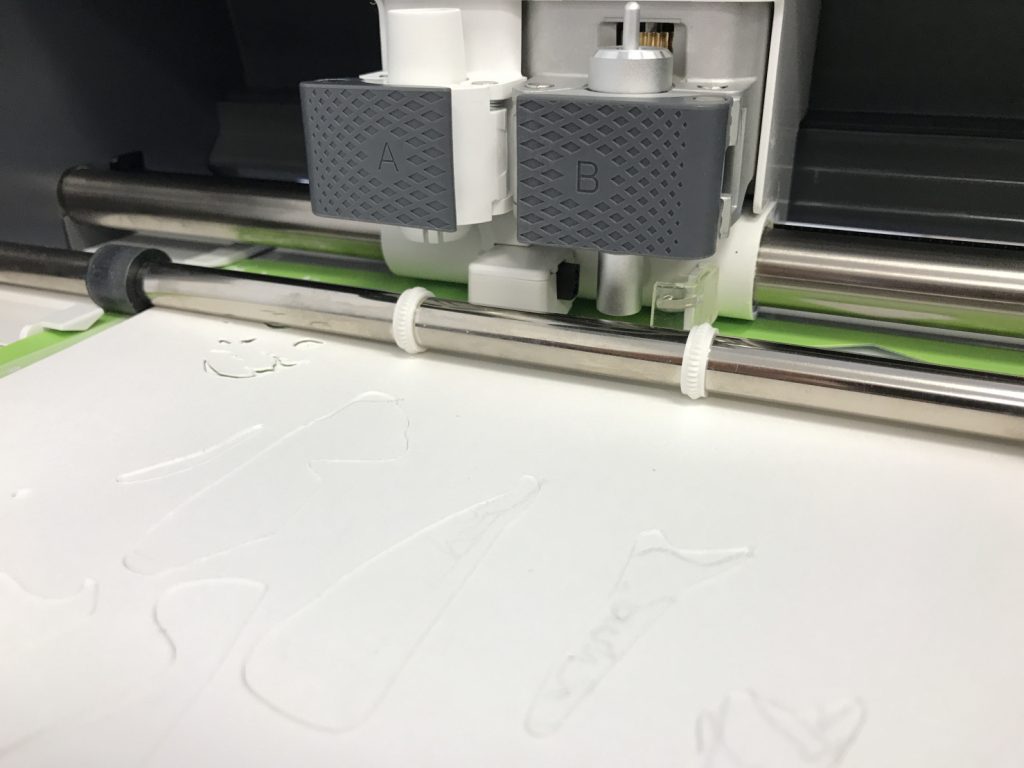
Vinyl cutting: The computer controls the movement of a sharp blade to cut out shapes and letters from sheets of self-adhesive vinyl, paper, felt or fabric. In some machine, the blade can also be swapped for a scoring tool or pencil.
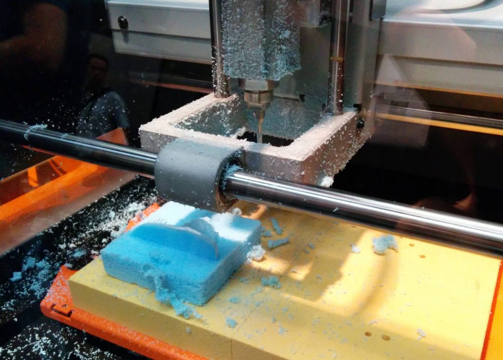
CNC machining: CNC machines use computerized drills and/or rotary cutting tools to cut and carve wood, stone, plastic or metal.
Vector graphics and digital fabrication
Vector graphics are defined by mathematical relationships and by points, lines, and shapes. They are not defined by pixels, the way a photographic image is. A circle created in vector software would be defined by a number of points, by an x/y position, and by other information, such as color, width of the stroke. In the Adobe Creative Cloud, Illustrator is the vector program. There are many other vector programs, Inkscape is an open-source application. In this class, we will be using Illustrator.
Vector files are used widely in digital fabrication. We will be using vector files to cut with the vinyl cutters and with the laser cutter. Generally it is important that the paths you create in Illustrator are closed paths, though there are exceptions.
Depending on what type of digital fabrication machine you are using, you may need to prepare your files differently. Stroke width and sometimes stroke color are important in files to be cut on a laser cutter, this does not matter for files to be cut with the vinyl cutter, but the file format that you load may be important.
While there are many other ways to make paths with Adobe Illustrator or other vector software, mastering the pen tool is extremely helpful. Students who take this course should have some experience with Illustrator, this is a quick review.
Drawing with the Pen Tool in Illustrator
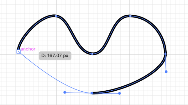
In a vector drawing program, lines and shapes are defined as paths made up of anchor points. An open path is a line, a closed path is a shape. There are 2 kinds of anchor points, corner points and smooth points. Corner points define straight lines, smooth points define curves. The smooth points have handles coming out of them that determine the arc of the curve.
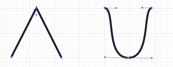
If you want to make an open path, click to set down corner points, click and drag to set down smooth points, adjusting the length of the handles to control the arc of the curve. When you have completed the line, hit the Return or Enter key.
To make a closed path, set down your anchor points. When you are ready to close the path, click on the first anchor point. The pen tool cursor will have a little circle next to it, indicating that it will close the path.
Combining Shapes with Pathfinder
There are a number of shape tools available in Illustrator, including rectangle, ellipse, You can combine these shapes to make more complex paths using the Pathfinder panel (Window Menu>Pathfinder).
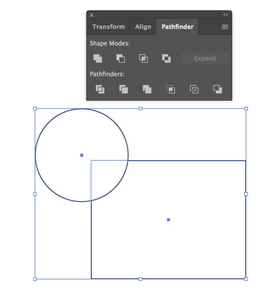
Draw the shapes on the Artboard, with them overlapping in the manner you want to combine them. To combine the shapes into one form, click on the first icon under Shape Modes. The result will look like this.
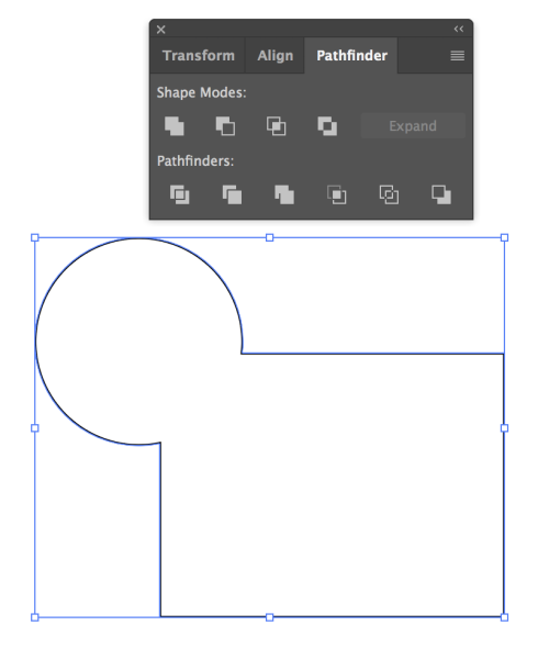
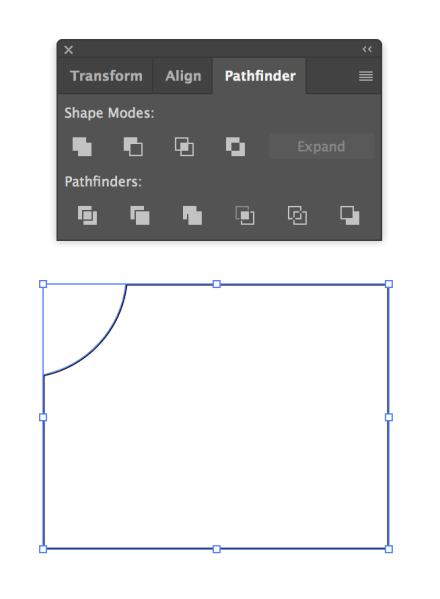
If you want to subtract one shape from another, you can use the Subtract Front icon, the second one under Shape Modes.
Combining Shapes with the Shape Builder Tool
You can also combine shapes with the Shape Builder Tool. This tool is in the tool palette. 
Draw 2 shapes on the Artboard. Make sure they are both select4ed. Select the Shape builder tool.
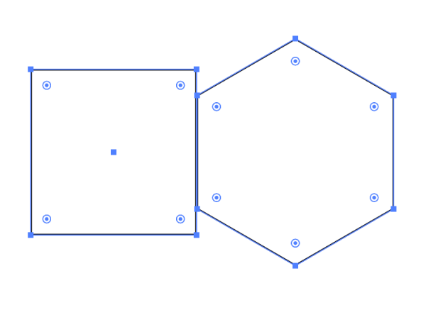
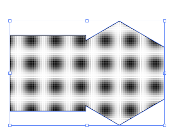
When you roll over the shapes, they will have a fine grid of many gray dots over them Click and drag over them with the tool, and the shapes will be merged.
Using the Vinyl Cutter
A vinyl cutter is a machine that attaches to a computer that cuts vinyl, paper and other light-weight materials. Vinyl cutters cut paths, so generally you will be preparing your artwork in Adobe Illustrator or another vector drawing program. There are many varieties of these machines, some are used professionally. We have 2 consumer models in the BMCC Maker Space, a Cricut Maker and a Silhouette Cameo.
Both of our vinyl cutters can load dxf files (AutoCAD Interchange file) into the software they use when cutting. They can cut other types of files, such as pngs or jpgs, but it is advisable to make sure you have saved your file as ai (Adobe Illustrator) then exported your files as dxf.
Vinyl Cutter Workflow Overview
- Sketch project on paper
- Prepare Illustrator files
- Make certain that your paths are all closed
- Save your file as .ai
- Export your file as .dxf
- Turn on Cameo or Cricut, attach computer
- Open software
- Load dxf in software
- Place paper on cutting mat and load mat
- Adjust settings for software (paper weight, paper size)
- Press cut button or send to machine
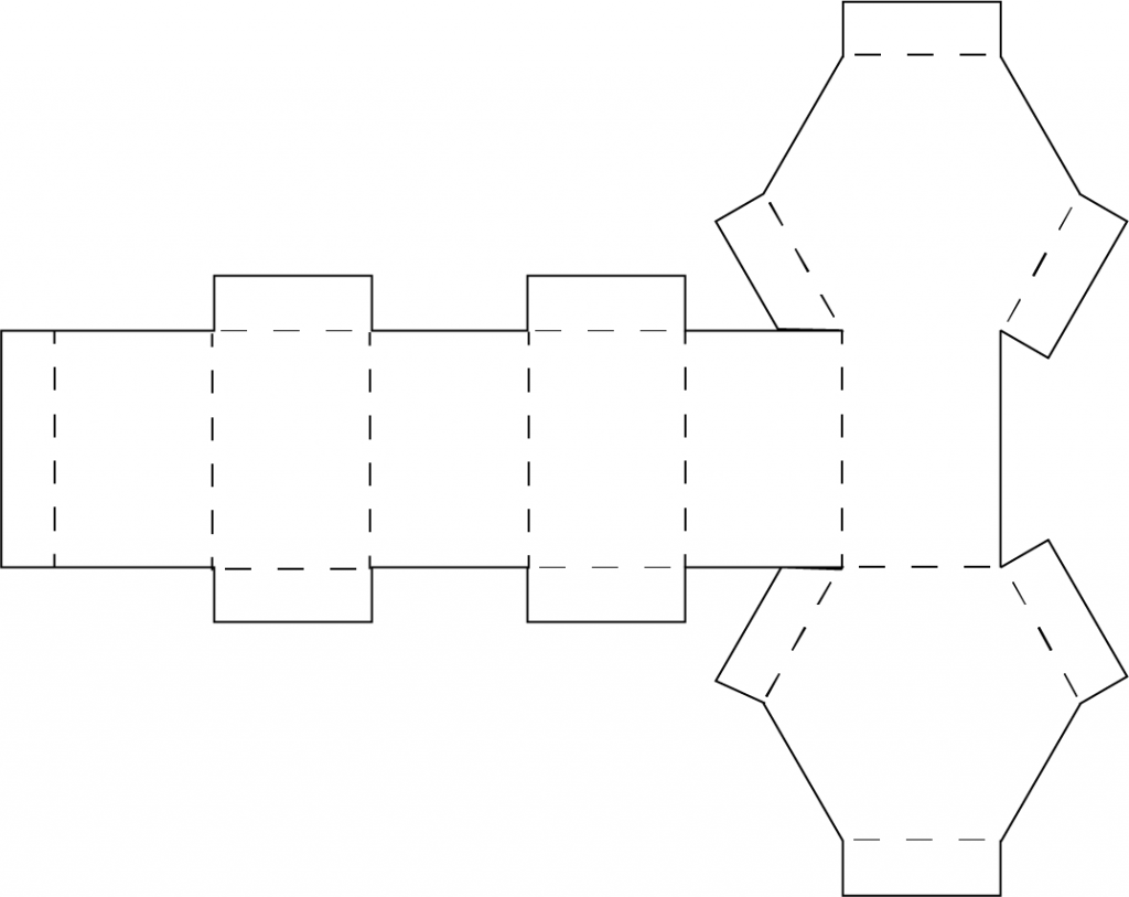
Using the Laser Cutter
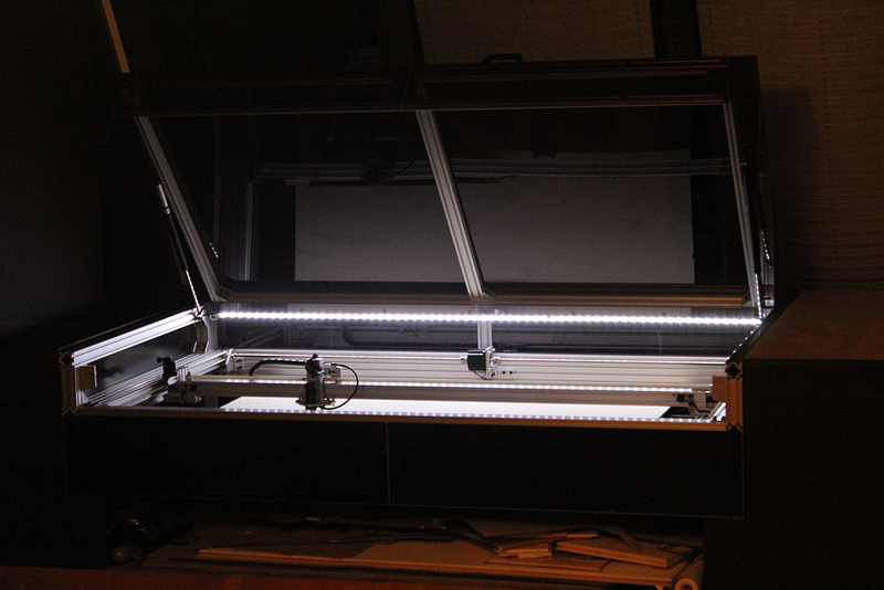
A laser cutter uses a laser to cut away materials. There are many varieties of this machine, with many industrial applications. The machine we have, the Epilog Mini 24, can cut cardboard, plexiglass, wood, fabric and other materials less than 1/4 inch thick. In addition to cutting, it can also etch materials.
Laser Cutter Workflow Overview
- Sketch project on paper
- Prepare Illustrator files
- Make certain that your paths are all closed if you are cutting a file
- Save your work as .ai
- Place your work on the laser cutter template
- Make sure paths that are to be vector cut use the proper stroke width.
Settings for Illustrator documents for the laser cutter
In order for the laser cutter to cut, you must have your document set up properly. We have provided an Illustrator template. If you are vector cutting a file, you must set the stroke width to 0.01. Files that are to be cut should have no fill, just a stroke, and that stroke must be set to the proper width.
If you are planning to raster etch a file, set the fill to black.
Only the CLT, lab manager or your instructor can cut files presently, but it is important that you understand how the laser cutter works and that you set up your documents properly. It is also a good idea to understand the basic settings for cutting and for etching different materials.
Vector Cutting settings
There are 3 things that must be set when you are vector cutting: speed, power and frequency.
Speed refers to how fast the carriage that contains the lens that focuses the laser on the material moves across the bed.
Power refers to the amount of laser power applied when the laser is firing.
Raster Etching settings
Speed the speed the carriage moves.
Power the amount of laser power.
Frequency the number of times the laser is firing.
How do you know what settings are appropriate for the material you are using? This material settings chart gives you a place to start, adjustments may need to be made. Our laser cutter is brand new, and frequently the recommended settings from Epilog need to be adjusted.
3D Modelling
3D modelling involves creating a representation of a 3D object with software. It can involve manipulating polygons, vertices and edges in a simulated 3D environment.
There are many different software applications for 3D modelling, from simple to extremely complex. Some are oriented towards creating models for objects to be printed, while other applications are oriented towards creating models for animation.
Tinkercad
The software we will be using in this class is Tinkercad. It is free, with a web based interface. Tinkercad has been designed to be easy to use to both create models and to export in a format that can be printed.
To use Tinkercad, you need to create an account for Autodesk, the company that makes the software. Click here to set up an account.
Tinkercad has many useful tutorials that are quite helpful when you are learning the software. This tutorial, Let’s Learn Tinkercad, walks you through navigating the workspace, moving rotating and scaling objects, making and manipulating groups and using the align tool. It is a good place to start.
This page will cover some basics of the workspace and some simple instructions to get you started. It is highly advisable for you to work through the Tinkercad tutorials as well. While Tinkercad is relatively simple for 3D modelling, it uses the terms as well as some of the methods of creating, revising and viewing 3D models.
Starting a design
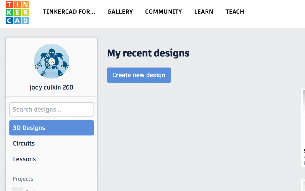
When you have created an account, there is a home page with a menu on the left side with your user name and icon, and buttons marked 3D Designs, Circuits and Lessons. Click the button labelled 3D Designs, then click the button marked Create new design.
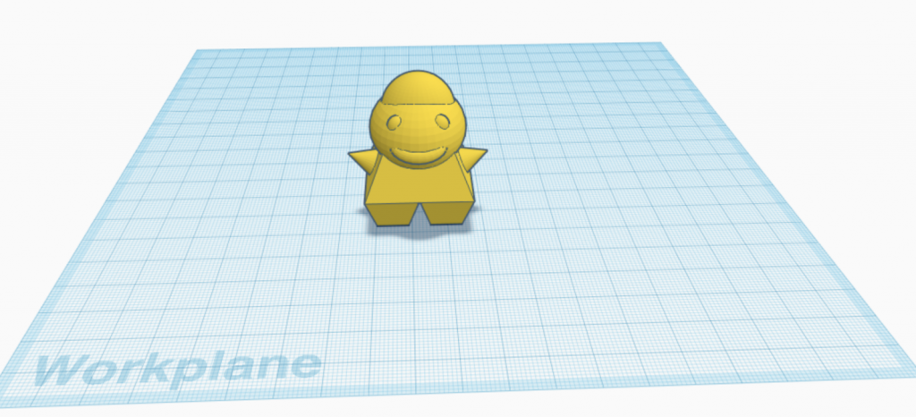
You will be in the workspace of Tinkercad. The grid, graph paper-like plane is called the workplane. Your view is called the camera.
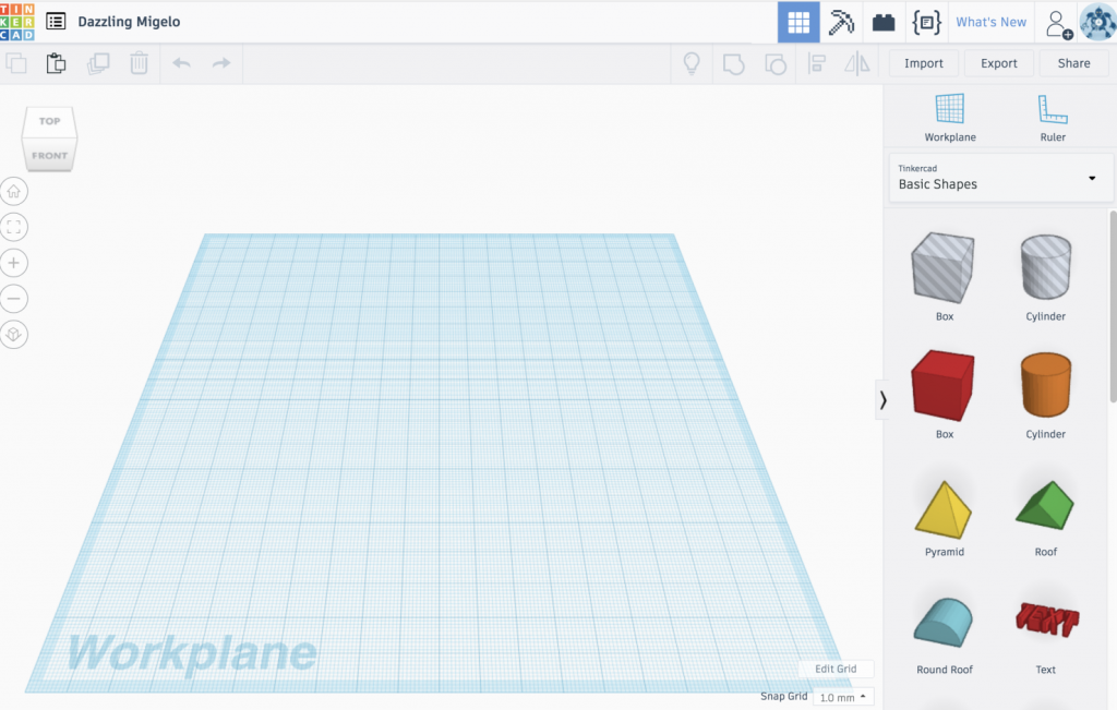
Navigating the Tinkercad interface
On the left side, there is a view cube and icons for setting the view to home, zooming in and out, and other viewing functions. Clicking on the view cube changes your view of the workplane: front, top, left, right, bottom. Try clicking the view cube and seeing how the orientation of the camera changes.
![]()
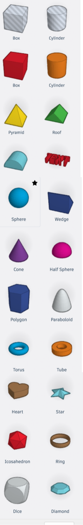
The shape menu is on the right hand side of the interface. This shows you the primitive shapes that you can select and drag to the workplane to combine and revise to create your models. Scroll through the menu to see all of the shapes, there are many.
Drag a box to the workplane. Use the view cube to look at each side. Try clicking the home and all the other icons in the menu on the left to see how it changes your view. You can also zoom in or out with the trackpad if you are using a laptop. If you are using a mouse, zoom in or out with the track wheel in the center of the mouse. You can pan left and right by holding down the right button of your mouse and dragging. By holding down the scroll wheel and dragging, you can reposition the camera.
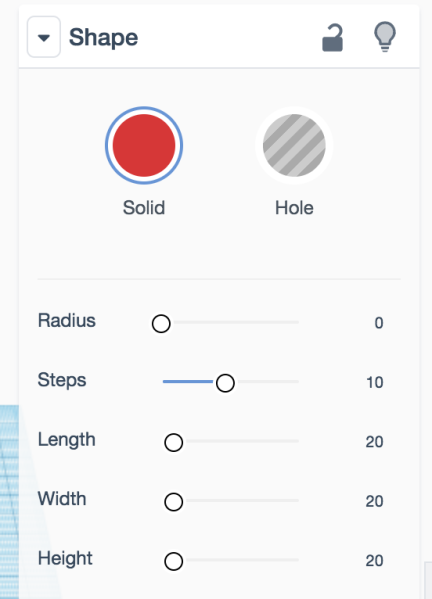
If you have a shape on the workplane and it is selected, on the top right side, you will see the shape menu. This menu tells you many of the properties of your shape, such as whether it is a solid or a hole, the length, width and height.
Translation: moving along the X, Y and Z axis
When you move an object in 3D space without rotating or scaling it, that is called translation.
- Moving an object left to right is translating it along the X axis.
- Moving an object front to back is translating it along the Y axis.
- Moving an object up or down on the workplane is translating it along the Z axis.
When you drag a shape in the workplane, you will see the numbers that indicate how far you have translated the shape, in centimeters. You can click on the shape to select it, then drag it forward, backward, to the left or right.
If you want to move an object up or down, click on the black arrow at the top of a shape when it is selected. You can move it above or below the workplane.
![]()
Rotating an Object
You can rotate an object around its 3 axes: X, Y and Z. When an object is selected, you can see the rotation handles for these axes. If you move over the handles with the cursor, you will see the rotation protractor, showing you the possible degrees of rotation for that axis.
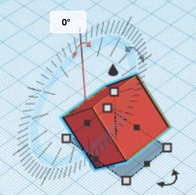
The Z axis is perpendicular to the workplane, it is relatively intuitive to rotate on that plane. The X and Y axes can be more confusing. Rotating along the X axis rotates a shape left-right. Rotating along the Y axis rotates an object front-back.
If the cursor is placed inside of the protractor, the shape will be rotating by 22.5 degrees. If the cursor is outside of the protractor, the shape will be rotated by 1 degree.
Try rotating the shapes in all three axes.
Scaling an Object
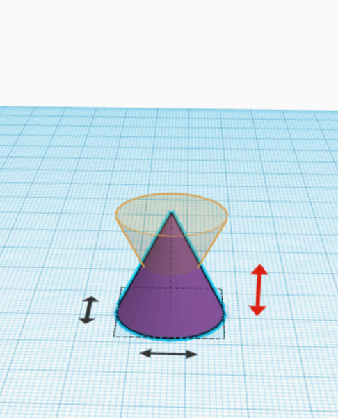
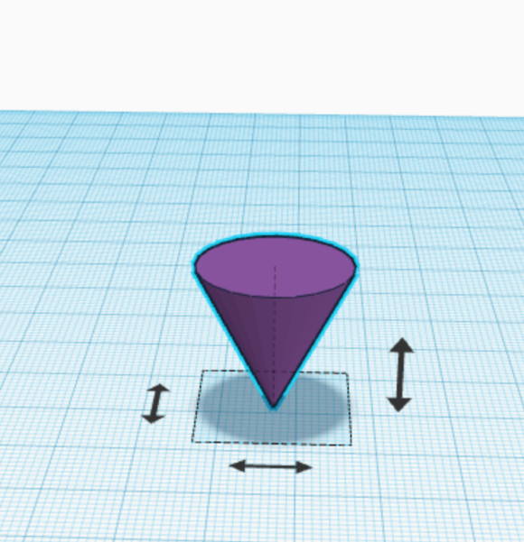
When an object is selected, you see 5 white squares and 4 black squares arranged around the object. These are the scaling handles. Move the cursor over them. If the cursor is over a black handle, you see the dimensions of the object along the X or Y axis. If you put the cursor over a white handle, you see the dimensions for both the X and Y axes, Put the cursor over the white handle at the top, and you will see the dimension for the Z axis.
Click on the white handle at the top and scale your object up and down.
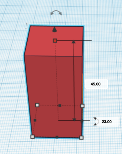
Next click and drag on one of the corner white handles at the base of your object and scale both the X and Y axes.
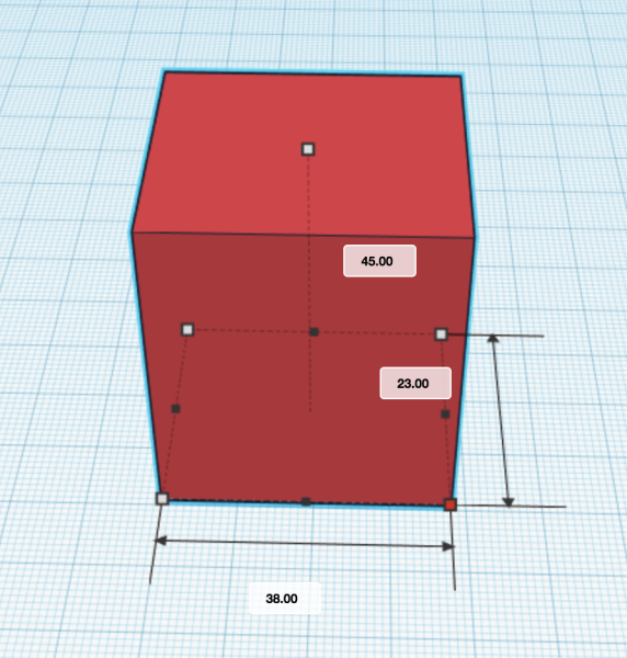
If you want to scale only in the X or Y direction, you can click on one of the black handles at the base and scale that way.
If you wish to scale proportionally, hold down the shift key, then grab any handle and drag. If you wish to scale around the center of the object, hold the alt key on Windows, command on a Mac. If you wish to scale proportionally about the center of an object, hold down shift and alt on Windows, shift and option on a Mac.
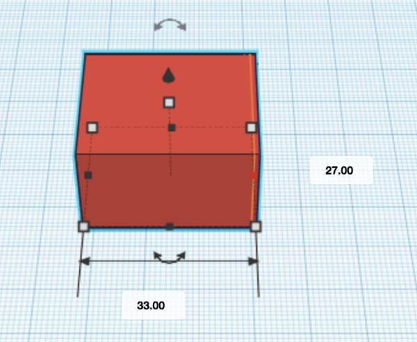
Skew by Rotating and Scaling
Sometimes you want to make a shape that doesn’t exist in the shape menu. By rotating and scaling an object, you can create new shapes. Try creating a parallelogram- how would you do it?
Grouping objects
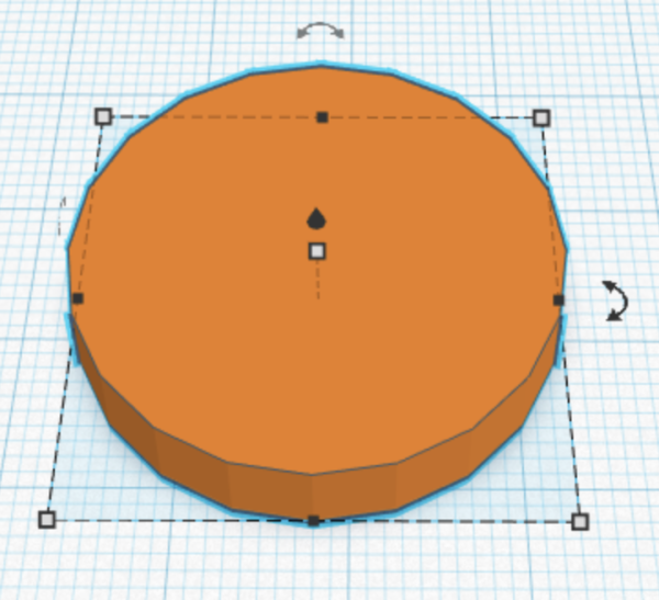
Most objects are made of a combination of shapes joined together. Let’s combine a few cylinders of different scales.

First, drag a cylinder to the workplane. Scale it proportionally, by holding down the shift key when you drag on one of the white corner handles, so it has a diameter of 30 cm. Then set the height to 5 cm by clicking and dragging the white handle at the top of the object.
Next drag another cylinder over from the shape menu.
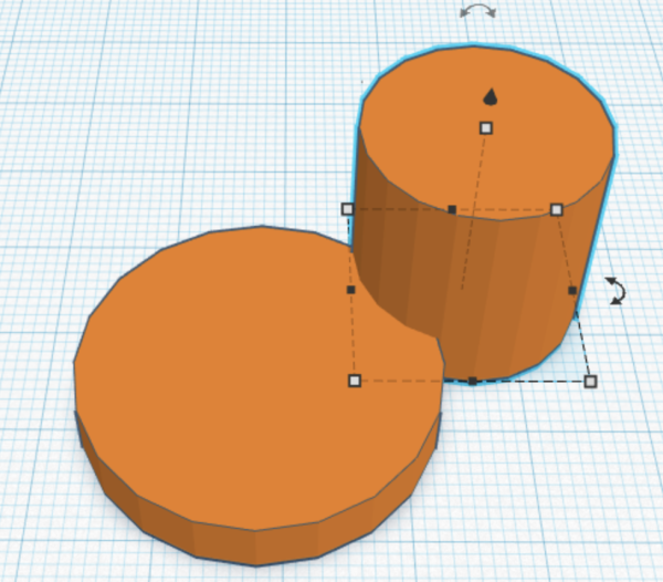
Scale the diameter to 15 cm (remember to hold shift down while dragging), then scale the height to 5 cm.
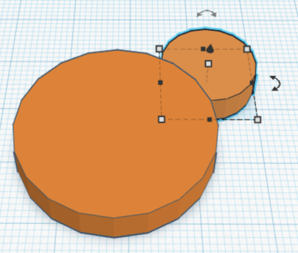
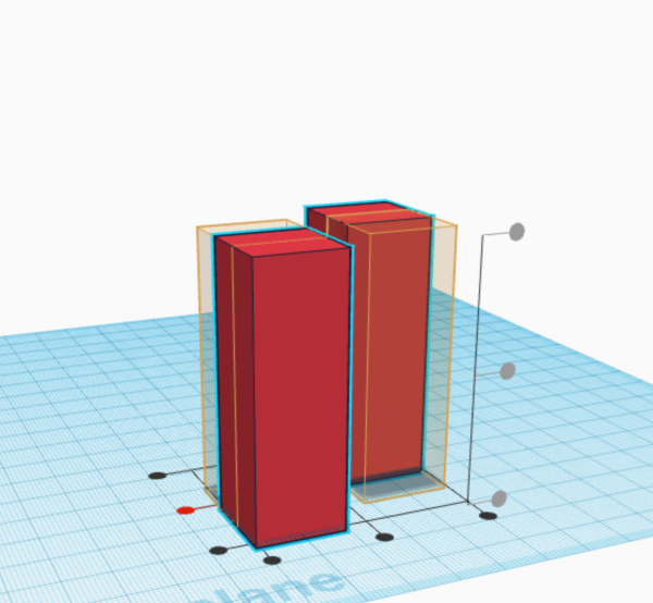
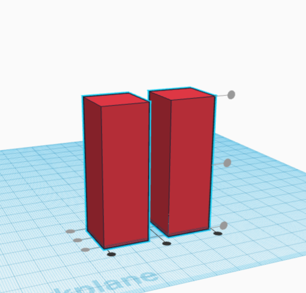
We want to make a copy of the smaller cylinder. There are many ways to duplicate a shape in Tinkercad. One of the simplest is to select an object, hold the alt key on Windows or the option key on a Mac, and drag. You will drag a copy of the original shape, position it at the other side of the large cylinder.
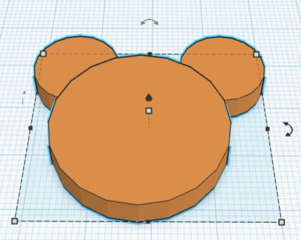
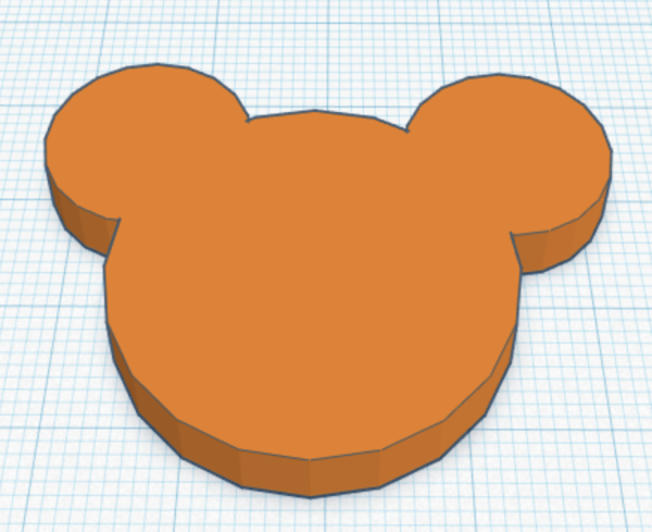
Now let’s group the shapes together. Make sure that all of the shapes are selected. At the top of the window on the right side of the interface, there are a number of icons. The icon below is the icon for grouping the selected objects. Click it, and the shapes on the workplane that you have select3ed will be grouped ihnto one object.

Combining Solids and Holes
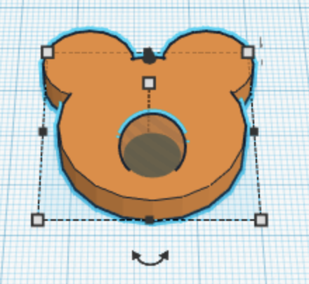
A 3D object may consist of positive and negative shapes. A negative shape is known as a hole. While building models, you will be combining shapes and grouped shapes with holes, to add hollow spaces to your model, for instance. Let’s add a hollow to the model we have created.
Drag a sphere to the workplane and position near the middle of the model.
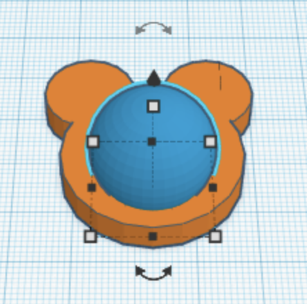
Resize the sphere to 10 cm in the X, Y, and Z axis. Click on the black arrow and pull the sphere up 2 centimeters.
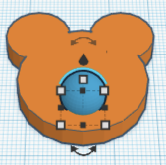
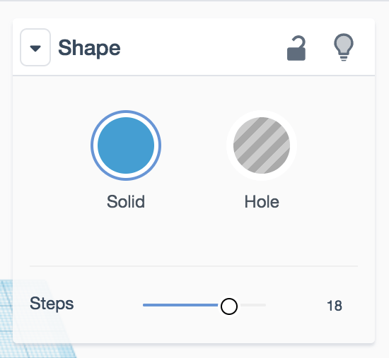
With the sphere selected, you will see the Shape Panel. There is an icon for Solid and one for Hole. Click the Hole icon. the object changes to a hole.
Aligning Shapes
As we have seen, creating complex shapes involves combining basic shapes. Perhaps you might need to align shapes to each other before you group them. This is easy to do in Tinkercad.
First select the shapes you want to align to each, by dragging over them, or shift clicking. Next click the Align icon at the menu on the upper right of the interface.
![]()
You will now see dots or handles around the selected objects that indicate how you might want to align your objects. There are handles on the X, Y and Z axis. You will see a preview of what it will look like when you click the handles when you roll over the handles.
When you click on the handle, the shapes will align along that axis.
Flipping shapes
Flipping shapes can also be very helpful when you are creating a model. To flip a shape, select it, then click on the Flip icon on the upper right side of the interface.
![]()
The object you have selected will have handles that look like arrows indicating the way the object will be flipped along the X, Y, or Z axis. If you roll over one of the arrows, you will see a preview of how the object will be flipped.
Once you click on the arrow, the object will be flipped.
Exporting
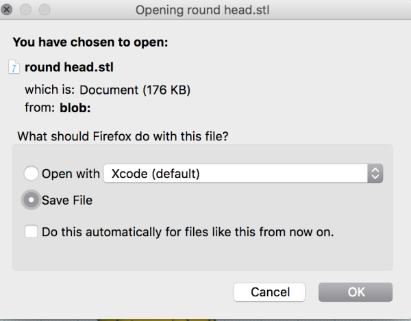
In order to print your model, you must export it from Tinkercad. You can export it as an .stl or .obj file. In most cases we will probably use .stl files to print.
To export, click the export button in the upper right menu. When you roll over it, you may see a tooltip.
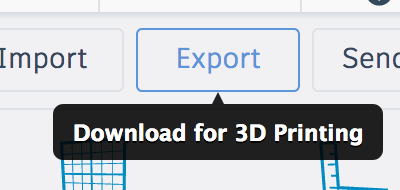
Next there will be a dialog box with buttons where you can choose to save your file as an .obj file or .stl file. Choose .stl.
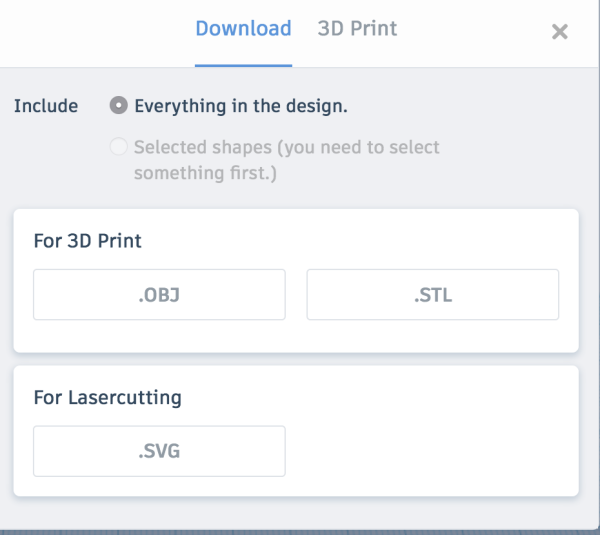
One more dialog box will appear. Click OK. Now your file is ready to be printed.
3D Printing
3D printing is an additive manufacturing process, in which objects are built from a succession of thin layers stacked on top of each other. Experiments in 3D printing started in the 1980s. 3D printing is now used extensively in industry and for prototyping. There are industrial and consumer printers widely available. Services such as Shapeways will print a 3D model in a range of materials.
3D printing techniques
There are many different 3D printing technologies. Here’s a list. This page has an overview about each of the techniques.
- Fused deposition modeling (FDM)
- Stereolithography(SLA)
- Digital Light Processing(DLP)
- Selective Laser Sintering (SLS)
- Selective laser melting (SLM)
- Electronic Beam Melting (EBM)
- Laminated object manufacturing (LOM)
In this class, we will be printing with a consumer printer using the Fused deposition modelling method (FDM). In this page, we will cover the basics here of how this type of printer works, the work flow for printing, and some tips to consider in preparing your models to ensure that they print properly.
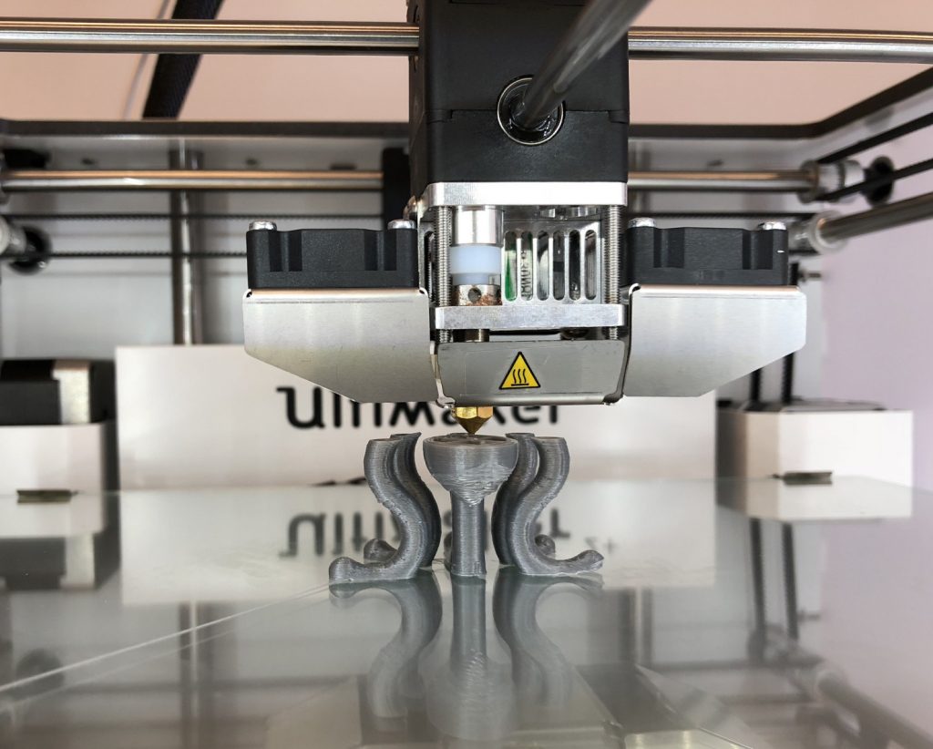
Basics of FDM printing
In FDM printing, the nozzle of an extruder moved by a carriage repeatedly deposits thin layers of plastic filament on a heated bed. Motors control the position of the bed and also the extruder. There are 2 types of filament commonly used, PLA and ABS. PLA (polylactic acid) is a biodegradable material made from corn starch. ABS (Acrylonitrile butadiene styrene) is fossil fuel based, non-biodegradable plastic. We will be using PLA exclusively.
Printing workflow with the Ultimaker
When you have finished creating your model in Tinkercad or whatever software you are using, export it as an STL file. If you are printing using the Ultimaker printer, open up the Ultimaker Cura software. Cura is a slicer software. It will create the G-code, the instructions that the printer will follow to build your model. (G-code is used in many digital fabrication methods, not just by 3D printers.)
Once you have launched the software, open up your model from the File Menu > Open File(s).
On the right side, there is a menu where you set properties for your prints. We will go over the settings in detail a bit later on.
If your model is selected (by clicking on it), on the left side you will see a menu that allows you to move, scale, and rotate the model, as well as other functions.
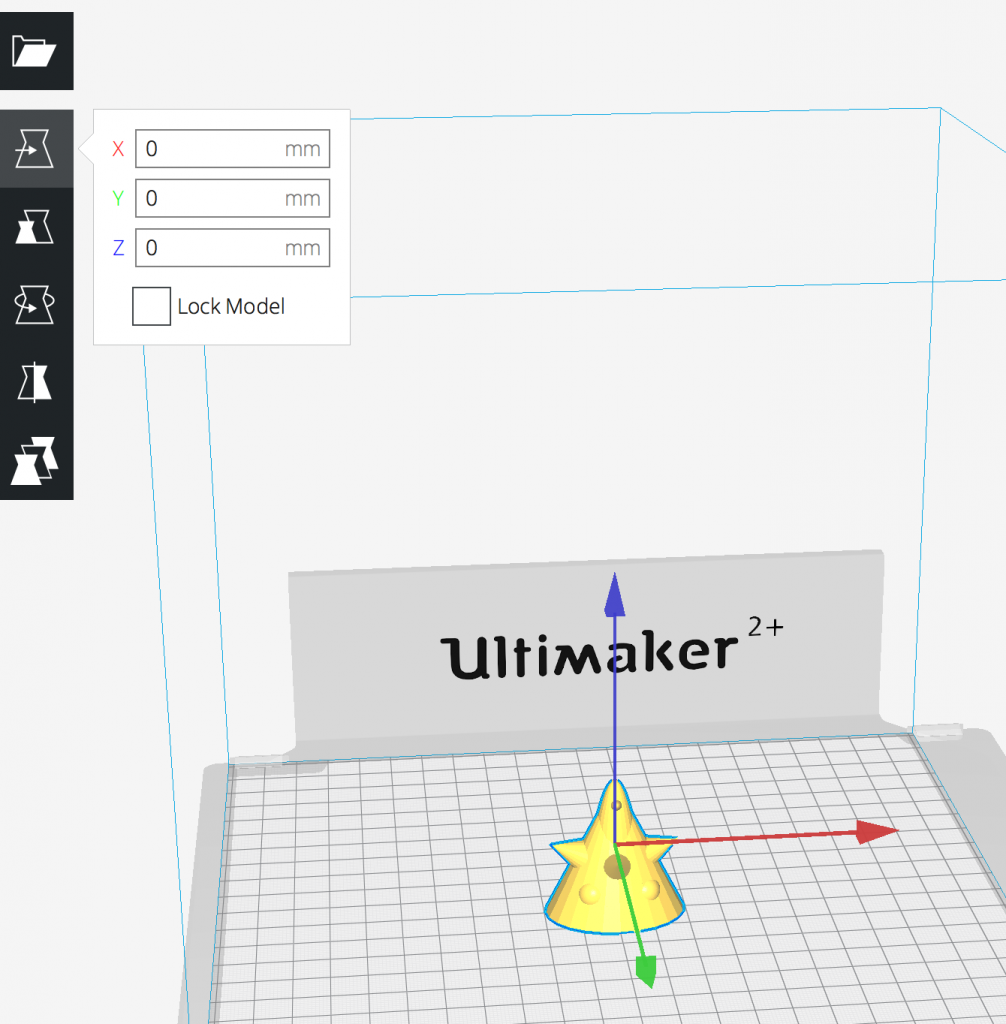
You may wish to scale, rotate or make another adjustments to your model. When you are done, look at the print settings on the right side of the interface.
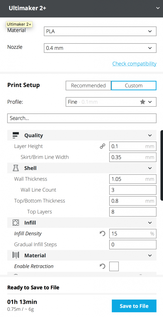
Print Settings
First the type of Material is selected (PLA). Next, the size of the Nozzle. The smaller the nozzle size, the finer the resolution of the print. However, the print time will increase if the resolution is higher. Profile: Fine. In Quality set Layer Height to 0.1, Skirt/Brim Width to 0.35
The Tinkercad to Ultimaker Cura Guide has a complete listing of all the settings to begin working with our Ultimaker 3D printers. We hope to have a guide for the Prusa here soon.
Most of the text and images in this chapter are taken from Jody Culkin and Anna Pinkas’ “MEA211 – Introduction to Digital Fabrication and Physical Computing” course/website.
Further reading/resources:
- What is Digital Fabrication:
- “Will 3D Printing Change the World” – video from PBS’s “Off Book” series
- ” 5 of the Biggest Challenges Facing Manufacturers in 3D Printing” – article by Apple Rubber
- “The spread of 3D models creates intellectual-property problems” – article from The Economist
- Vector graphics and digital fabrication
- Vinyl Cutting
- Laser cutting
- 3D modelling
- Tinkercad
- Let’s Learn Tinkercad. Tutorial that covers the basics of adding shapes, combining them and navigating the interface.
- 3D printing