What is physical computing?
Physical computing refers to the process of building physical interfaces that respond to the analog world. This is done by building circuits with micro controllers, wires, sensors, LEDs, motors etc. and controlling them with a piece of custom-made software (i.e: “Turn the LED on when the number sent by the photocell sensor is less than 100”). Physical computing is a great way of introducing or reinforcing programming concepts, and exploring how they can be applied to non-screenbased applications. But it has also been used beyond the educational realm – by artists, to support ALS patients, for immersive installations, experimental music, fashion, and to test water quality.
While there are a lot of similarities between robotics and physical computing, the latter is focused on creating interfaces that explore the human body’s relationship to the digital world (rather than building robots that can function without human or environmental input).
Using a Microcontroller
What’s a Microcontroller?
A microcontroller is a small computer that can take in information from inputs such as sensors and switches and control outputs such as lights, motors and other computers. Microcontrollers are widely used in many different ways; DIY and robotics, art installations, industrial applications, and the internet of things.
When you are using a microcontroller, or in our case a microcontroller platform, there are two components: hardware and software. The hardware includes the microcontoller and its input and output pins, and any input or output devices you want to attach to it. The software is programs you write that control the microcontroller and the devices you have attached to it.
In this class we will be using the Arduino microcontroller platform. It was developed by a team of teachers to help their design students who were not engineers create physical interfaces.
![]()
The Arduino has an IDE, (integrated development environment), that is free and downloadable from the Arduino site (download it here). This is a set of software that allows you to write code, then upload it directly to the Arduino.
Arduino Uno
There are many different versions of the Arduino but we will be using just one, the Arduino Uno.

In order to program the Arduino, download the Arduino IDE and install it (detailed instructions on downloading and installing are here). The laptops we have in our Maker Space already have the software installed. Connect the Arduino to the computer with a USB A-B cable. If you have a newer Macintosh laptop, you will have to use an USB-C to USB adapter.

Parts of an Arduino Uno
Let’s look a bit more closely to the parts of the Arduino. We’ll look at the left side first.

Reset Button: This button will restart the code currently uploaded on your Arduino. The reset button may be in a different location on your board than in this diagram, but it is the only button.
USB Port: The USB port takes a standard A-to-B USB cable, often seen on printers or other computer peripherals. The USB port serves two purposes: First, it is the cable connection to a computer which allows you to program the board. The USB cord will also provide power for the Arduino if you’re not using the power port (described below).
Voltage Regulator: The voltage regulator converts power plugged into the power port (described below) into the 5 volts and 1 amp standard used by the Arduino. BE CAREFUL! This component gets very hot.
Power Port: The power port includes a barrel-style connector which allows for either power straight from a wall source or from a battery. This power is used instead of the USB cable. The Arduino can take a wide range of voltages (5V – 20V) but will be damaged if power higher than that is connected.
Now let’s look at the rest of the board.

Built-in LEDs: The LEDS indicate that there is power, and if your Arduino is sending or receiving data.
Digital I/O pins: The holes on this side of the board are called the digital input/output pins They are used to either sense the outside world (input) or control lights, sounds, or motors (output).
TX/RX pins: Pin 0 and Pin 1 are special pins labeled TX and RX. They control how information is transmitted to and from a computer. It is best not to use them empty.
ATmega328P, black chip: The black chip in the middle of the board is an ATmega328P. This is the “brains” of the Arduino: it interprets both the inputs / outputs and the programming code uploaded onto your Arduino.
Power and ground pins: All of the pins related to power are located here. You can use these pins to run power from your Arduino to your breadboard circuit.
Analog pins: These pins take sensor readings in a range of values (analog), rather than just sending whether something is just on or off (digital).
Settings in the software
We have seen a bit about the parts of the Arduino and we have seen that we program it through the Arduino software. Before we start programming the Arduino, we have to set a couple of settings in the software to ensure that the Arduino can communicate with your computer.
Load the Arduino software. Once it is loaded, go to the To do this, go to the Tools menu, select Board. From the fly out menu, select Arduino Uno/Genuino.

It is also necessary to specify a Serial Port for your Arduino to communicate with the computer. A Port is a channel of communication which connects your Arduino and the computer. On a Windows machine, go to the Tools Menu, select Port then select the COM port that is specified. It should look something like the screenshot below.

Once you have connected the Arduino to the computer and set the version and the port, you are ready to start programming the Arduino.
Programming the Arduino
As we have seen, the Arduino IDE is free and can be downloaded from their site. Detailed instructions for installing and configuring the IDE can be found here.
What’s an IDE?
An IDE, or integrated development environment, is a software application that allows you to write code and test that code out in the programming language the IDE supports.
If you have experience programming, you may have used another IDE to write, test, debug, and turn your code into something the computer understands. If you haven’t, the Arduino IDE is a good place to start, as it is relatively simple and easy to understand.

The Arduino team has designed an IDE for use with their devices that has the features you need. It has a built-in code editor, which is a program used to write the code files that you create when programming. You can test your code in the IDE and solve problems with the help of a message area that shows errors in your code and a console that provides more detail about the nature of these errors. It has buttons so you can check your code, save it, create a new code window, upload it to your Arduino and more.
![]()
The sketch
In the Arduino IDE, your program is called a sketch. The sketch is the basic unit of Arduino programming. The Arduino IDE supplies example sketches, that cover many of the things you can do with an Arduino. Let’s open, save, then upload a simple sketch called Blink.
First, connect your computer to the Arduino with a USB A-B cable. Open up the Arduino IDE. When it is open, go to the File Menu > Examples > 01.Basics > Blink. This will open up the Blink Sketch.

Let’s take a look at the buttons in the IDE, at the top of the sketch. The verify button checks your code for errors, the Upload button sends your code to the Arduino, New creates a new code window, Open opens a previously saved sketch and Save saves your sketch.

Here’s a screenshot of the Blink sketch, with the three main sections annotated.
Comments are used to write notes to anyone who might read your code. This might be you, when you return to a sketch you created earlier, or others who you are sharing your code with. Comments have no effect whatsoever on how the computer interprets the text and are only there to remind you or clue someone else in on what you intended to do, or how the program functions as a whole.
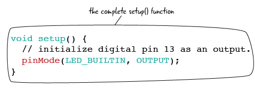
The setup() function is where you set initial conditions for your code. setup() happens only one time, when you run the code or turn on your Arduino.
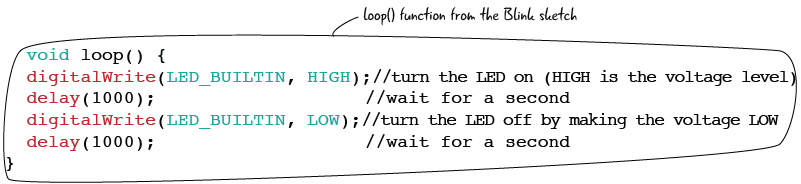
The loop() function is where you put code that you want to run over and over again.This is generally where all of your code that creates functionality lives. We will see, for example in the Blink sketch, the code that turns the LED on and off is here.

Save and rename the sketch!
After you’ve taken a look at the Blink Sketch, save it and give it a new name. File Menu > Save As > MyBlink for example. You don’t want to write over the example files and also you want to make adjustments to the example file to understand how the code is working. Saving early and often is always a good practice.
Verify and Upload
Let’s verify the sketch, then upload to the Arduino. Click the Verify button to check your code. Even though this is an example sketch, it is good to get in the habit of checking your code. There will be a message in the bottom of the window that tells you a bit of information about your sketch. If there was a problem, it would also note it here. After verifying, you can upload your code, Make sure your Arduino is attached to the computer and that you have configured it properly. Then press the upload button. The LED on the Arduino near pin 13 should start blinking on and off.


setup() and loop(): the guts of the code
Now let’s look a bit closer at setup() and loop(). We have seen that setup happens once and loop happens over and over again.

Inside of the setup() function, there is a line of instructions to the Arduino. It tells the Arduino to set the pin on the Arduino that is attached to the built-in LED on the board to be an output. In other words, pinMode() tells the Arduino to set LED_BUILTIN (pin 13 on the Arduino Uno) to be an OUTPUT.
If we look at loop(), we see several more lines of instructions inside the function, These lines of code are what is turning the LED at pin 13 on and off. digitalWrite() sets LED_BUILTIN to HIGH, turning on the LED. delay() pauses the Arduino for 1000 milliseconds, or one second. The next line, digitalWrite(), sets the LED_BUILTIN LOW, or turns off the LED. This is followed by another delay(), which pauses the Arduino for 1000 or one second.
Try adjusting the amount of time that the LED is on and off. How do do that? Create a new pattern, perhaps a short time on, a long time off, a long time on. How would you do an SOS signal?
Building a circuit
The circuit is the basic building block for any electronics project. A circuit includes all of the electronic components required for a task as well as wires or another material which will let the electricity flow between the connected components. Electronic circuits describe a complete and closed loop.

There are two main parts that make up a circuit: conductive lines and components.What are components? LEDs, transistors, resistors, diodes, and all of the parts that control the flow of electricity or have another function in our circuit. Conductive lines are often metal threads or wires, as metal is a good conductor of electricity.

The Breadboard
Components are often attached to each other on a solderless breadboard. What’s that? A solderless breadboard has rows and columns of metal strips encased in plastic with a grid of holes called tie-points on the top. It allows us to quickly build circuits without having to permanently connect the components (by soldering, for example). Here’s an “x-ray view” of a breadboard.

There is a pattern to how the metal strips are arranged on a breadboard. There are long strips along the left and right of many breadboards that are used to attach power and ground in a circuit. These long columns are called busses. The power bus is marked with a red plus sign, the ground bus with a green, blue or black minus sign.

This drawing shows how components are attached on a breadboard; the leads of the components are in the same row of tie-points.

Connecting the breadboard to an Arduino
How do you connect a breadboard to an Arduino to build a circuit? Let’s build a circuit that connects a breadboard with an LED and a resistor to an Arduino.
You will need these parts:
- Arduino Uno
- solderless breadboard
- USB A-B cable
- LED
- 220 Ohm resistor
- jumpers
A note about LEDs
An LED (light emitting diode) has an orientation, or a positive and negative lead. An LED must be placed into a circuit properly, with the positive and negative lead oriented properly. How do you know what is the positive and negative side? The positive side has a longer lead. It is called the anode. The negative lead is shorter and called the anode. Also, the negative side of an LED often has a flatter side at the bulb.

Start building!
Before you start building, make sure your Arduino is not attached to your computer. Never make changes to a circuit when power is attached.
Attach jumpers from the 5V power pin on the Arduino. Your teacher should have some jumpers, they are pieces of wire used to make connections between components. You can make your own jumpers as well, by using 22 gauge hook-up wire and stripping the coating off the ends.
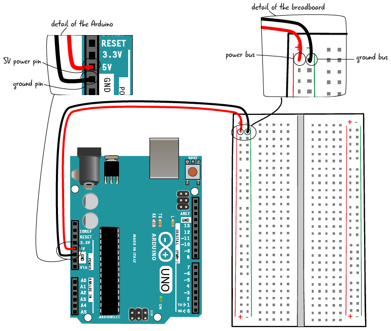
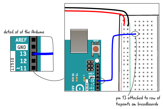
Next attach a jumper from pin 13 on the Arduino to a row of tie-points on the breadboard.
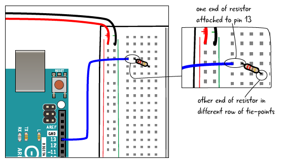
Place one end of a 220 Ohm resistor in the same row of tie-points as the jumper from pin 13, and the other end in a different row of tie-points.
Now let’s place the LED in the breadboard. Put the anode (long leg) of the LED in the same row of tie-points as the resistor. Put the cathode (short leg) of the LED in another row of tie-points.

Now you have built the circuit! Hook up the Arduino to your computer. If you have already downloaded the Blink sketch, your code is loaded on the Arduino, and the LED should start blinking right away. If you haven’t downloaded the Blink sketch, open up the Arduino software. The Blink sketch is at the File Menu > Examples > 01. Basics > Blink.
Digital Input and Output
We use computers every day that have inputs and outputs. On a computer, the inputs might include keyboard and a mouse. The outputs are a screen and speakers. On the Arduino, a digital input might be a switch or button, the output an LED. Inputs send messages to the microcontroller/Arduino. Outputs receive messages from the microcontroller/Arduino.

Why do we want to add an input? Interactivity! So far, we have been able to control the LED by code, but it is not interactive, the Arduino turns the LED on and off with no user input. We will learn how to turn the LED with a button.
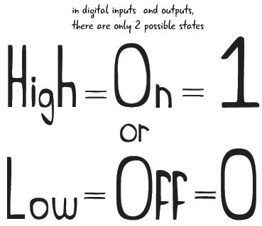
It’s important to understand that a digital input or output can only have 2 possible values, on and off. In digital inputs and outputs, HIGH = On = 1. LOW = Off = 0.
Adding a button to a circuit
Let’s start with the circuit we built to run the Blink sketch. Make sure that power and ground are connected to the busses on the breadboard. Pin 13 should be attached to a row of tie-points that has one lead of a 220 ohm resistor. The other end of the resistor should be attached to the anode (positive end) of the LED. The cathode (negative end) of the LED should be attached to a jumper going to ground.

Once you have made sure that your circuit is built properly, we will move on the adding a button.
Buttons and switches
There are a million different ways to trigger electronic devices or turn something on. Switches and similar on/off devices activate everything from televisions, to music equipment, lights, even your kitchen appliances. How does a switch work?
All switches work on the same basic principle: it either “closes the circuit” and turns something on, or “opens the circuit” and turns something off. When the switch is closed, electricity can flow through; it cannot flow through when the switch is open. The schematic symbols for a switch illustrate how this works. (A schematic is a simplified drawing that uses symbols to represent the electrical relationships in a circuit.)

We are using a momentary pushbutton switch in our circuit. When you hold down the button, it completes the circuit. When you let go, the switch opens up and the circuit is no longer complete.
Here is a drawing and a schematic of the pushbutton:

Step by step: add button
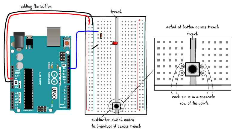
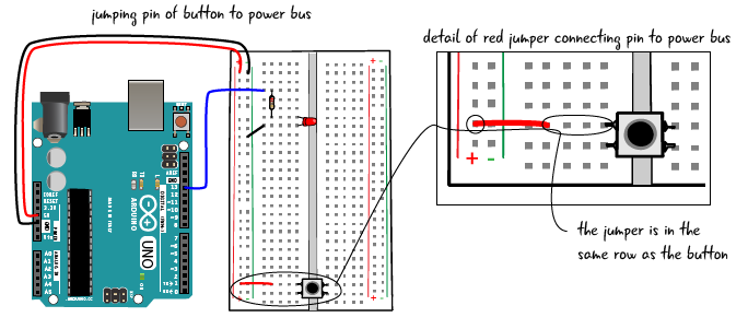
Now let’s place the button on the board. It will go over the trench in the breadboard.
Next we will add a jumper from the power bus to one of the leads of the pushbutton.
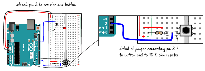
Add a 10k resistor from the ground bus to the other side of the pushbutton.

The final step is to connect the pushbutton to the Arduino, Attach a jumper from pin 2 to the same row of tie-points that as the resistor and one of the leads of the pushbutton.
Once you have added the jumper connecting the Arduino to the breadboard, you are ready to connect the Arduino to a computer and upload a script. Connect with a USB A-B cable.

Open up the Arduino IDE. Open this script: from the File Menu > Examples > 02.Digital > Button. Save as, with a name like MyButton.
Click the Verify Button to make sure there aren’t any problems with your code or the connection or settings in the software. If all is well, then click the Upload button. Now try pressing the button. Your LED should turn on and off.
While there may be adjustments depending on what type of device you are turning on or off, this procedure should work generally for any kind of digital input or output.
Analog Input and Output
We have seen that digital information only has two possibilities, on and off. Analog information, on the other hand can hold a range of possible values. We perceive the world as a stream of analog information via our eyes and ears and other senses. By using analog information with our Arduino, we can respond to the users’ input in a more complex fashion. We can control the brightness of an LED, setting it to shine brightly, glow dimly, or show any range of values in between.
Analog information is continuous and can hold a range of possible values. It is quite simple to attach sensors and variable resistors to the Arduino so we can capture information with a range of values, not just on and off. Some examples of sensors would be photoresistors, which capture information about light levels, or thermistors, which capture information about temperature. There are many, many types of sensors available that can give us information about the world around us that can be attached to the Arduino.
We will learn how to add a potentiometer to a circuit to control the brightness of our LED, from the dimmest glow to the brightest.
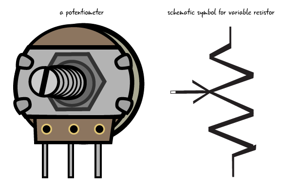
What’s a potentiometer?
A potentiometer, sometimes called a pot, is a knob or dial that can be turned to increase or decrease the amount of resistance depending on how far, and in which direction, it is turned. Potentiometers come in many sizes and shapes. We will be using a 10k ohm potentiometer in our circuit.
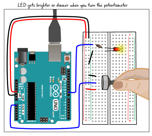
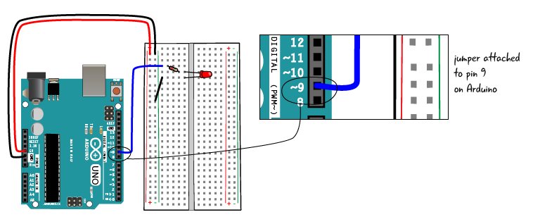
In order to build our circuit, first we will make a basic circuit using an LED, a 220 Ohm resistor, some jumpers and an Arduino Uno. This is quite similar to the basic circuit we have used in our other examples, with one important difference. The Arduino pin attached to the LED is pin 9, not pin 13.
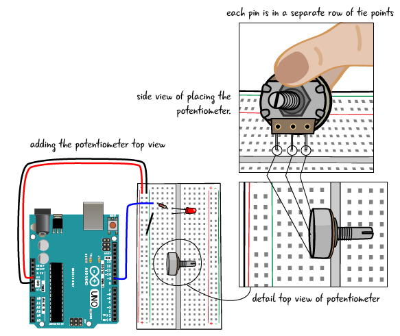
Now we will attach the potentiometer. A potentiometer has 3 pins. In our circuit, we will attach the middle pin to a pin on the Arduino, one of the outer pins to the power bus, and the other outer pin to the ground bus. It doesn’t matter which outer pin goes to power and which one to ground.
We will place the potentiometer parallel to the trench as depicted in the drawing. Each pin of the potentiometer is in a separate row of tie points, with an empty tie point between each of the pins. Orient the potentiometer facing away from the Arduino, with the dial over the trench, as shown below. This will make it easier for you to reach the potentiometer to turn it and to integrate it into the rest of the circuit.
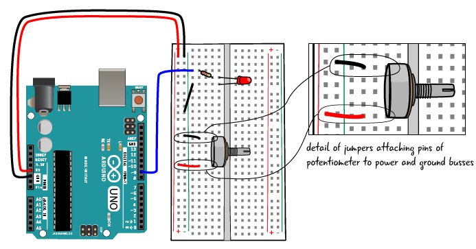
Now we’ll attach the potentiometer to the power and ground busses on the Arduino.
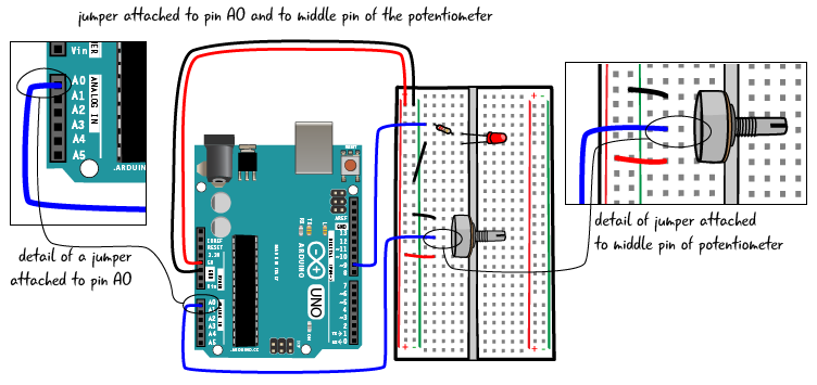
Finally, we will attach the middle pin of the potentiometer to pin 9 on the Arduino.
Upload the sketch
Now that you’ve built the circuit, attach your Arduino to a computer. From the File Menu > Examples > 03.Analog > AnalogInOutSerial. Save the sketch, renaming it as something like MyAnalogInOutSerial. Click the Verify button, then click the Upload button. Turn the potentiometer. Your LED should go from dim to bright, depending on how far it is turned.
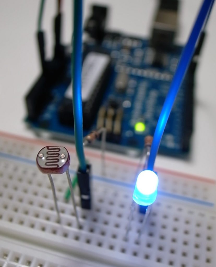
Using a photoresistor
Let’s look at how to use a sensor to test something about conditions in a room. We’ll look at a photocell, also known as a photoresistor. A photoresistor can test for light levels in a room. Before you start making adjustments to the circuit, make sure that it is not connected to a computer or other power source.

Setting up the circuit for a photoresistor is slightly more complicated than using a potentiometer. To set up this circuit, first take out the potentiometer from your breadboard. Then place the photocell, or photoresistor into the breadboard, with one end attached to pin A0. There is no polarity or direction in a photocell, you can place either one of the leads in that row of tie points. Place the other lead in another row of tie points.
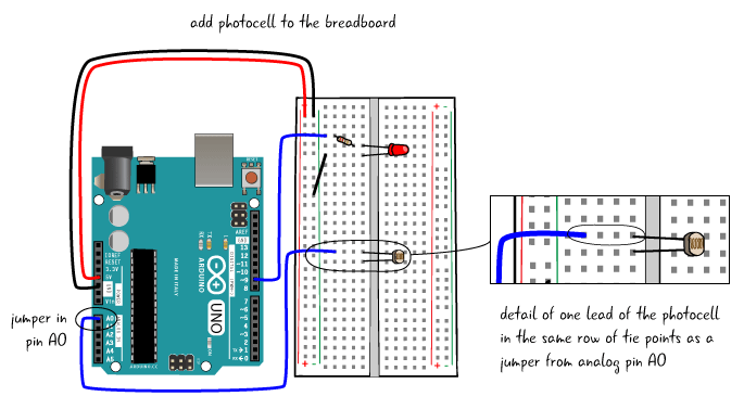
Next we will attach the other lead to power with a jumper as shown in the drawing.

Add a 10K resistor to the circuit. One lead is in the same row of tie points as the jumper to pin A0 and one lead of the resistor. The other end of the resistor is in another row of tie points, and jumped to the ground bus.

You can attach the computer back to the Arduino now. If you have not made any changes to the code, you should be able to run the same sketch on the Uno as you downloaded and saved when you built the potentiometer circuit. If your hand is covering the photocell, the LED will be shine more dimly, the more light that shines on it, the brighter the LED will light up.

Most of the illustrations and text in this chapter are taken from Jody Culkin and Eric Hagan’s book “Learn Electronics with Arduino: An Illustrated Beginner’s Guide to Physical Computing”. Some of these resources are also available for free at arduinotogo.com.
Further reading/resources:
- What is physical computing?
- “The Measured Man” – article from the Atlantic
- “Massimo Banzi: How Arduino is open-Sourcing imagination” – TED talk
- Physical Computing page at ITP NYU
- Using a Microcontroller
- Building a circuit
- Digital Input and Output
- Analog Input and Output